1 Introduction
Can a mains cable be used as a ‘filter’ to block the entry of Radio Frequency Interference (RFI) into domestic audio equipment from the mains? Are some fancy forms of cable generally better at doing this? Some recent papers[1][2][3] have been published that present measurements on some mains cables. These consider some specific cables which – it has been claimed – may offer better RFI rejection than ordinary mains cables. The idea being that the specific way the cables are constructed does provide higher RFI rejection. The contents of the papers has been said to provide a ‘scientific’ basis for the claims about the specific cables. I’ve been curious about this topic for some years, so I decided to investigate and see what I conclusions I could reach...
2 The Detective Story
The general issue of RF interference being conveyed or picked up by mains cables is a complex one, particularly in the UK where mains sockets provide three wire, nominally unbalanced, power for domestic equipment like audio amplifiers, etc. For simplicity I will focus on a fairly simple approach to examine the RF behaviour of mains cables when conducting such interference.
 Figure 1
Figure 1 illustrates the kind of arrangement I will consider. Here mains power is taken from a power socket on the wall, and carried by a length of cable to the audio equipment. In terms of conventional transmission line theory we can regard the wall socket as a ‘signal source’ where some of the ‘signal’ may actually be RF interference fed along the house wiring to the mains socket. The mains cable can be regarded as a transmission line that guides the signal power in the form of an EM wave (and the related voltages and currents). At the other end of the mains cable the Audio equipment can then be regarded as a destination which acts as a load for the presented signals. However we may tend to find that the source and load have RF impedances which differ from the characteristic impedance of the cable. In general, any propagating signal which encounter such an impedance mismatch may have some of its energy reflected. In this case we have two locations where such partial reflections can occur. These are at the ends of the cable. Multiple reflections can then occur as some of the input energy repeatedly echos back and forth between the mismatches at the two ends of the cable run.
This behaviour can be analysed using transmission line methods. To avoid too many equations here I’ve put the details of the mathematical analysis on another page as an appendix, so please refer to that if you wish to see the details of how the model works. Here I will just discuss the consequences and the kinds of results we can expect.
For the sake of illustration, consider a situation where the wall socket (source) and audio amplifier power input (load) both happen to have an effective impedance of 50 Ohms, and we have a choice between two specific mains cables. Note that the choice of the impedance values at this point is purely for the sake of example and they may not represent most real domestic cases. I will return to dealing with that issue later on.
 Figure 2
Firstly, there are a series of peaks and dips in the response as we change the frequency. The frequency spacing between adjacent peaks or dips is actually determined by the combination of the physical length of the cable and its EM wave propagation velocity. A longer cable (or a slower wave velocity) would tend to reduce the change in frequency between adjacent peaks or dips. Nominally, the peaks occur when the propagation length of the cable is an integer number of half-wavelengths.
Secondly, the difference in power transfer level between maxima (peaks) and minima (dips) for a given cable depends upon the level of mismatch between the cable impedance and the impedances (of the destination and source) which links together. The 80 Ohm cable example shows much smaller dips than the 3 Ohm cable because it reflects less power when linked to a 50 Ohm source or load.
In fact, figure 2 shows behaviour which will be familiar to many RF/microwave engineers. When they want to convey wideband signals along cables with minimal loss they try to use a cable whose characteristic impedance is a close as possible to the impedance of the source and destination. Ideally, they would be matched – i.e. the cable, source, and load would all have the same impedance value.
The clear implication of the above is that we can turn around the usual requirement of RF engineers and say that if we wish to reject signals and prevent them from entering the destination we should deliberately choose a cable whose characteristic impedance is a different as we can make it from the source and load impedances. The arrangement will then tend to ‘reflect’ or reject RF signals at most frequencies. On that basis we might conclude that Figure 2 tells us that a mains cable whose characteristic impedance is 3 Ohms will be better at preventing RF from entering the load than a 80 Ohm cable. The snag is that this assumes the source and load impedance really are 50 Ohms since that is the case considered for Figure 2.
3 What is appropriate?
The questions that seem worth asking here are: Is it likely that domestic mains sockets usually have source impedances for RF which are close to 50 Ohms? And do the power supplies for domestic audio/video equipment also present input impedances at RF of around 50 Ohms? Is this value an appropriate choice if we wish to use the results to choose a mains cable for normal domestic use?
I must admit that this seems doubtful to me. Particularly as I’d tend to expect the input impedance for a PSU to modulate as it switches between conducting and not conducting during each mains (or switch mode) cycle of operation! Unfortunately, the values of the mains (wall socket) and PSU impedances do matter, as can be illustrated by the following examples.
 Figure 3
 Figure 4
The general point the above examples illustrate is that the results obtained will depend upon the source and load impedance as well as the properties of the mains cable. So although a given cable may give ‘better’ RFI rejection than another with a specific choice of source and load, the outcome could reverse when the same cables are used with some other source and load that have different impedances. 50 Ohms is a standard choice for laboratory equipment and cables, so may be convenient for measurements purposes. But unfortunately the results may not be the same when the same cable is used in domestic circumstances. Without knowing the details of the wall socket and PSU RF impedance we therefore can’t tell if such measurements are a good guide to what will happen in a home audio system.
This is a double problem if we want to exploit cable impedance to help prevent mains-carried RF interference from getting into domestic audio equipment. When designing or building cables the makers would need to know what values of RF impedance were typical or common for domestic wall sockets and audio equipment. And then any individual wanting to choose a mains cable would need to know if their own wall socket and choice of equipment had impedances that were typical, or not. Unfortunately, it seems quite plausible that the output RF impedances of domestic wall sockets varies from one socket to another, and also with frequency. This probably also varies according to what other equipment is plugged in elsewhere in the house, or even next door! Hence this does seem like a very hit-and-miss way to try and reduce RF interference from the mains.
4 Cable Constructions
Some of the expensive mains cables offered for sale to audiophile tend to use fancy-sounding materials and constructional methods. The cables are often presented with a series of technical-looking claims about how they work and what they do. These sometimes include descriptions of all kinds of mysterious (or magical?) ‘Effects’ which may seem to confound boring old-fashioned physics and electronic engineering. Yet as the above indicates, you can actually explain how a cable could affect RF transmission or rejection using quite basic conventional analysis.
Broadly speaking, there are two main ways to change the characteristic impedance properties of a cable. One involves altering the physical geometry of the cabling. The other is in the choice of some of the materials. Let’s start by looking at geometry...
For the sake of simplicity and clarity I’ll ignore for now the fact that in the UK we often use three-wire mains cables that include an earth/ground wire. So I’ll start with just two wires.
 Figure 5 Simple Twin-Wire cables.
 Figure 6 Twisted Pairs used in parallel.
Each of the twisted pairs will have a series resistance. Since we are using three similar pairs in parallel, the resulting combination will exhibit about one-third of the overall series resistance of one of the pairs used alone. Similarly, each twisted pair will have a series inductance, so placing three in parallel can be expected to reduce the overall series inductance by a factor of about three. Finally, each individual twisted pair will have a shunt capacitance between its wires, so using three in parallel can be expected to increase the total shunt capacitance by a factor of three. In practice the changes in values won’t be exactly a factor of three. This is because there will be EM field interactions between the twisted pairs. But overall, we can expect using a set of pairs running in parallel to reduce the series resistance and inductance and to increase the shunt capacitance. The cable inductance and capacitance have a relationship with the characteristic impedance of a transmission line. So we can expect the overall arrangement to have a characteristic impedance that also falls by something like a factor of three. For example, if each individual twisted pair has an impedance of 100 Ohms, then 3 of them in parallel can be expected to have an impedance more like 100/3 = 33 Ohms. Hence running sets of wires in parallel like this can be expected to affect the RF transmission or rejection behaviour when used as a mains cable. In general, the more pairs we run in parallel, the more we can change the resulting overall characteristic impedance of the resulting cable.
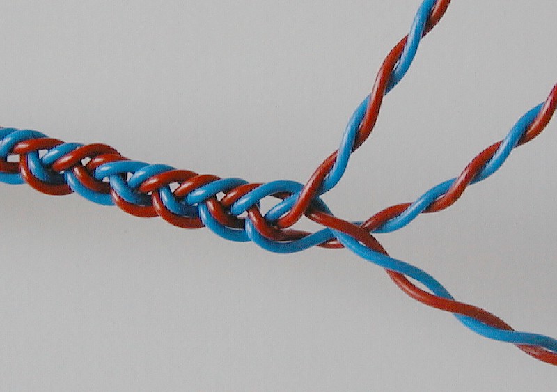
Photo of three twisted-pairs braided together.
The lower arrangement in Figure 6 illustrates three twisted pairs braided together closely. A photo of this kind of construction is shown above. The close proximity of the pairs to each other will alter the results so we can’t expect all the properties to change by precisely a factor of 3. But the overall result does tend to be a drop in characteristic impedance. Braiding or weaving cables is convenient for practical reasons. It also helps reduce the risk of RF being picked up from the surroundings although I will ignore that here and continue to focus on mains conducted RF. The braiding or weaving tends to make the routes of the individual conductors even more ‘around the houses’ than using simple parallel pairs. This tends to slightly increase the resistance, capacitance, and inductance, thus slowing down the propagated EM waves a little. Hence as well as having low characteristic impedances such cables also tend to display relatively low signal propagation speeds.
For the above reasons it is plausible to argue that such braided or woven cables, and various other constructions that essentially connect a set of pairs of wires in parallel will have RF properties that differ from more conventional forms of mains cable. Hence it is certainly possible for a manufacturer to construct cables with a low characteristic impedance. It is also possible for someone to make a series of laboratory measurements on such cables using signal generators and measurement kit with a standard impedance like 50 Ohms. The results may show that – under these test conditions – the novel cable with low impedance provided higher rejection of RF conduction than a conventional cable. Unfortunately that in itself does not establish the RF rejection will always be superior in normal domestic use. The problem is a straightforward practical one. Without evidence that tells you the RF impedance of your particular mains socket or audio unit PSU it becomes difficult to decide if a given cable’s impedance would make it a good choice in your own domestic system.
Using a series of paralleled pairs of conductors, and arrangements like braiding of weaving, aren’t the only ways the geometry of the cable can be altered to change the impedance and EM wave velocity. There are also other ways to alter behaviour by choosing materials that affect the EM fields between the conductors. The main ways to do this are to change the dielectric insulators, or to employ magnetic materials.
The choice and thickness/shape of the dielectrics nominally used for insulating the wires can change the intensity or pattern of the Electric fields between and around the conductors. This changes the amount of capacitance each metre length of cable will exhibit. Increasing the capacitance with dielectric materials tends to reduce the characteristic impedance and slow down the velocity of EM waves.
Standard types of mains cable don’t deliberately include any materials which have very large magnetic properties. But some special ‘audiophile’ mains cables employ ferrite materials. The presence of ferrite tends to have two main effects. One is to increase the inductance per metre. This tends to increase the cable impedance and slow down the EM wave. Another is that the ferrite can introduce an extra loss mechanism as power is absorbed by having to keep driving the magnetic domains in the material. This behaviour may sometimes be argued to provide a useful amount of reduction in the amount of RF interference conveyed by the cable. Losses of this kind tend to increase with frequency, so might be expected to have little or no effect at 50 or 60 Hz, yet enhance attenuation at RF.
Unfortunately it isn't always clear if the amount and type of material used in some of the audiophile cables actually does produce a significant amount of RF attenuation in normal use. As with the questions regarding mains wall-socket impedances, etc, I’ve not yet seen any reliable data on this. And there is also a problem with assuming the ferrite will always work as may be assumed. This is because the mains cable will also be carrying a significant 50/60 Hz (and harmonics) current, and the tendency for ferrite materials to ‘saturate’. What this means is that above a given magnetic field level the ferrite material will have all its internal magnetic domains aligned with the applied field. Increasing the field intensity then has little further affect on the ferrite. In essence, the ferrite then ceases to have much influence and might just as well be absent when it is saturated. So the problem here is that if the cable uses small amounts of lossy ferrite to absorb any unwanted RF, that may only happen when the mains current level is low enough not to saturate the ferrite material. Again, I’ve not yet seen any reliable data dealing with this question for the behaviour of any audiophile mains cable. So it remains unclear if such cables do, in domestic practice, work as may be implied by simple descriptions of the behaviour of ferrite materials and their ability to dissipate RF energy.
5 Multi Modes
For the sake of simplicity the above assumes the mains power supply only requires two connections – typically to a ‘live’ and a ‘neutral’. So the analysis assumes any RF interference is in the form of a difference in potential between these two connections at the source (mains socket). In practice in the UK the domestic mains arrangements are generally more complicated. The wall socket will provide three connections – the third being the ‘earth’.
In principle the 3-wire UK mains assumes that the supplied power voltage at 50 Hz is presented on the ‘live’ connection with the ‘neutral’ nominally at about 0 Volts. But in practice the large currents flowing in mains wiring mean that the non-zero resistance of the wires causes the ‘neutral’ connection to have a potential that also varies at 50Hz. Some of this voltage on the neutral connection of a house wall socket may be due to currents flowing though the mains distribution system outside the individual house. So for safety and other reasons the UK mains provides an ‘earth’ connection which is intended to be a low resistance link to zero voltage or ‘ground’ potential. In the absence of any problems there should be no mains power current flowing in the earth wires to cause a significant departure from the wall socket earth connection being at zero potential.
As a result, the mains cable actually in UK domestic systems often have three wires, not two. This means we have can various modes of propagation for unwanted RF interference. e.g. you may get RF voltages between live and earth or earth and neutral rather than live and neutral. These pairings may have different source impedances or be presented with different impedances when they reach the audio equipment. The usual analysis of a two conductor transmission system like an RF ‘twin feed’ also tends to assume that the signal is balanced. i.e. that the voltages on the two conductors vary in opposition. So when there is a given voltage on one conductor, the voltage on the other is equal equal in size, but opposite in sign. But in reality the mains 50Hz potential is unbalanced, and that may apply to some RF interference.
Because of factors like the above the situation is likely to be quite complex, and can be expected to vary from one domestic setup to another. All this introduces variables which mean that the results obtained by a maker of cables in simple live-neutral test bench measurement may not cover all domestic cases. As with the question of the wall socket and PSU RF impedances it is essentially impossible to decide on this without someone first having published the results of a large series of measurements on the situations in UK homes so we can know what ‘target’ a cable maker should be aiming to deal with! And any individual would then need to determine if their home is different to the norm.
6 General Conclusions
Given all the points I consider I am sceptical about the idea we should choose a ‘special’ mains cable for the specific purpose of acting as an ‘RF filter’. My own view is that simpler and perhaps cheaper methods are widely available and would probably be more likely to succeed. I would be more inclined to employ those if I was worried about mains-conveyed RFI. Various component companies can provide mains filtering units, etc. at relatively modest prices. If you wish to filter the mains input, then my suggestion would be to buy a mains filter unit, not a new mains cable!
In fact, my own experience is that well made domestic audio equipment generally does not need to have additional RFI protection for its mains input. Indeed, if it does, my reaction is to be concerned that the audio equipment is unsatisfactory and consider replacing it with another design! I do agree with the idea that choosing a mains cable that has a characteristic impedance very different to the impedance of the wall socket and the PSU could be expected reject some RF interference. The snag would be to ensure that the impedances involved really did represent a significant mismatch in the specific domestic case where you were encountering RF problems – and also to ensure that the interference was not at one of the peaks in the resulting pattern of peaks and dips!
Jim Lesurf
3rd Nov 2009
[1] Russ Andrews response to ASA Ruling. Initial announcement with extract of test results. Dated 19th Sept. 2008.
Obtained from http://www.russandrews.com/downloads/CableTestPremRes.pdf
[2] Interference and Distortion reducing capabilities of Woven PowerKords (TM)
Ben Duncan Dated 16 Feb 2009.
Author’s reference WovenCableDemProof-V1.53-29Dc08.doc Rev.No. 1.52
Obtained from http://www.russandrews.com/images/articles/OriginalResearchPaperVersion16Feb09.pdf
[3] Diagrams and Figures for Reference 2
Obtained from http://www.russandrews.com/images/articles/WeavePaperGraphsDoc.pdf