head.gif - 47Kb


front.jpeg - 91Kb

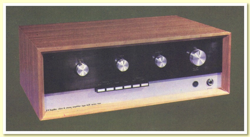
The A21 Series 2.


The ‘Series 2’ version of the A21 appeared just a matter of months after the original Richard Allan and JES A21. The new amplifiers looked quite similar to the original. The easiest way to recognise it was that the font panel now displayed, “J. E. Sugden class A stereo amplifier type A21 series two”, whereas the JES original simply had, “J. E. Sugden stereo amplifier”. The specifications were also changed. The most obvious change being in the rated maximum output power. This was now 12 Watts sinewave into 8 Ohm loads instead of the 10 Watts into 6 Ohms of the original.

The specifications of the A21 series 2 were as shown in the table below.

Max o/p Power into 8 Ohms at clipping 12 Watts per channel
THD at 10 Watts 0·25%
THD at 0·5 Watt less than 0·01%
Frequency and Power Response +/- 1dB 30Hz - 20kHz
Output to Tape Recorder 150 mV
Input sensitivity: Radio / Tape / Aux inputs 150mV 200 kOhms
Disc 1: Magnetic Cartridge input (RIAA) 2·5mV into 68 kOhms
Disc 2: Ceramic Cartridge (Flat) 50mV
Overload capability 25 dB on Disc
Noise (30 phon weighting) 200mV inputs -80dB
Noise (30 phon weighting) Disc 1 -70dB
Noise (30 phon weighting) Disc 2 -65dB
Rumble Filter (built into RIAA) 18dB per Oct below 30Hz
Bass Control +/- 14dB at 40Hz
Treble Control +/- 14dB at 10kHz
HF Filter 12dB per Oct above 7kHz
Power Consumption 70 Watts
Size 400 x 130 x 230 mm
Weight 11 Kg


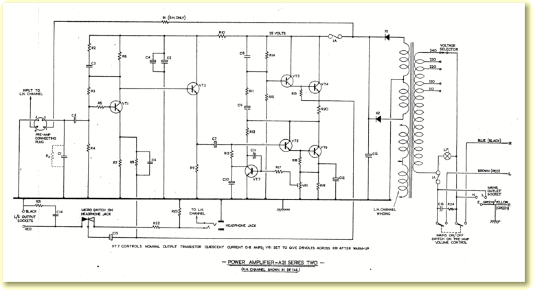
However perhaps the most significant changes were ones that weren’t listed in the specifications. These were to the circuit arrangements, making the amplifier easier to build and giving more consistent results.

smdiagram.gif - 31Kb


The above is a small image of the circuit diagram of the A21 series 2. Click here if you wish to see a more detailed image and list of component values..

The new circuit implemented the following changes:
If you have read the webpages on the original Richard Allan and JES A21 you will know that their circuits included a set of four diodes per channel. These – and some associated resistors – had to be very carefully selected to make a ‘matching set’ for each individual amplifier. This was a time consuming and frustrating process. OK for making one or two amplifiers on an amateur basis, but a nuisance when making amplifiers for commercial sale. By changing the output devices and making other improvements, the series 2 version no longer needed these carefully selected sets of diodes to be able to work reliably. As a result, the amplifiers were easier to make, and the results more predictable and consistent.

Device Max Voltage Max Current Max Power Max Frequency
BD121 35 V 5 A 45 W 60 MHz
BDY38 40 V 6 A 115 W 1 MHz


The table displayed above compares the maximum safe ratings of the BD121 and BDY38. It can be seen that the BDY38 has higher ratings. In particular, it can safely dissipate over twice as much power as the BD121. One reason for this is that the BDY38 has a better thermal path inside its package, making it easier to keep the device temperature down in use. In effect, at the same power dissipation, using the same heatsink, the BDY38 will, internally, run cooler than the BD121. As well as enabling use at higher powers, this helps break the vicious circle that can cause thermal runaway. The result is that the system is less prone to thermal problems. Hence it no longer needed a ‘fix’ like the use of selected diodes to control the bias and help prevent runaway.

inside.jpeg - 112Kb

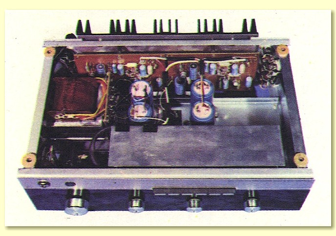
Internal view of A21 series 2.

The BDY38 works over a more limited frequency range than the BD121. This is a reflection of its more ‘robust’ construction which helped it to cope with higher powers than the BD121. In a Class B or AB design the use of devices that respond slowly can lead to symptoms like crossover distortion. However in a Class A design, problems due to the slower response of the BDY38 are less likely to arise, particularly in designs like the early Sugden amplifiers which only use modest amounts of feedback.

PvsRser2.gif - 17Kb


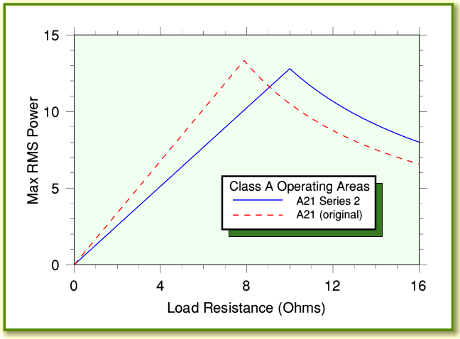
The A21 series 2 used a quiescent current of 0·8 Amps and a rail potential of 35 Volts. The original A21 used a current of 0·92 Amps and a 32 Volts. The nominal Class A areas of operation are shown for each amplifier in the diagram displayed above. The lower quiescent current of the series 2 means that the maximum Class A power into low load resistances is less than for the original A21. But the higher rail voltage provided increased powers into higher load resistances.

By comparing the printed specs for the original A21 (10 Watts into 6 Ohms) and the series 2 (12 watts into 8 Ohms) you might conclude that the series 2 was more powerful overall. However so far as Class A operation is concerned, the above diagram shows a different story. For loads up to about 8 Ohms, the original A21 should have been able to provide more Class A output power than the series 2! In practice, though, the performance into low resistances may be limited by the power supply rather than the actual amplifier output stages. So comparisons of this kind have to be treated with caution.

It is also worth noting that although rated at 12 Watts into 8 Ohms, the quiescent current of 0·8 Amps meant that for sinewave test signals the series 2 could actually only deliver about 10 Watts of Class A power into an 8 Ohm load. This indicates that at the rated output of 12 Watts into 8 Ohms the amplifier was out of pure Class A operation. In fact, both amplifiers may have been able to deliver higher powers than their Class A limit into low load resistances, but the series 2 was probably better at this than the original design. Hence the series 2 probably was less limited in terms of useful maximum power than the original, despite the restrictions on Class A operation.

The A21 series 2 remained on sale until it was replaced by the next generation of JES amplifiers at the Harrowgate Audio Fair in 1972


back.gif - 332 byteshome.gif - 1276 bytesnext.gif - 332 bytes