Many years ago I used to design audio amplifiers for a living. During that time, and on various occasions since, I suspected there was a ‘secret society’ for loudspeaker designers, called SCAMP. This is the Society for Cruelty to AMPLifiers! The evidence for this was the weird and wonderful impedance characteristics of many loudspeakers, and the headaches these give the power amplifier designer. To see what I mean, read on...
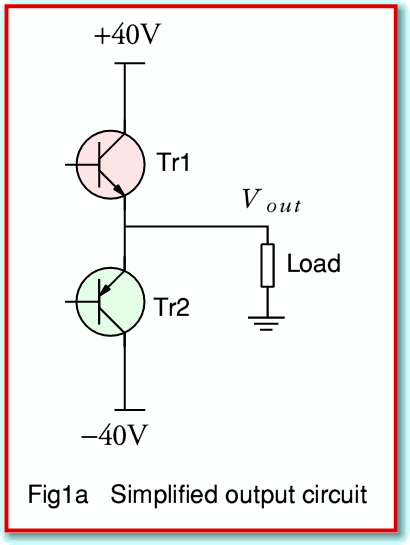
Most audio power amplifiers use an output arrangement equivalent to the simplified one shown in Figure 1a.
Here the voltage and current supplied to the output ‘load’ (in practice, the loudspeaker) is provided by a pair of devices. One is connected between the load and a line held at a positive voltage. The other is between the load and a line held at a negative voltage. By adjusting one transistor or the other we supply the load with current and obtain the required output signal voltage.
For the sake of example, I’ll use a design intended to provide around 80 to 100 Watts into an 8 Ohm load. This means I’ll choose ± 40 Volt power lines. I’ve picked values in this way because makers tend to specify – and reviews often measure – how much power can be supplied into an 8 Ohm resistor. Unfortunately, this misses SCAMP’s dirty work.
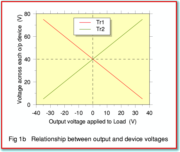
Consider the voltages experienced by the output device labelled Tr1. One of its leads is linked to  V, and another lead is connected to the output. This means that that when the output voltage is, say,
  V, then there will only be
  V across Tr1. But when the output is
  V, there will actually be
  V across the device. When the output voltage supplied to the loudspeaker varies, the voltages across the output devices also vary. The relationship is plotted in Figure 1b, with the red line showing what happens to Tr1, and the green line Tr2.
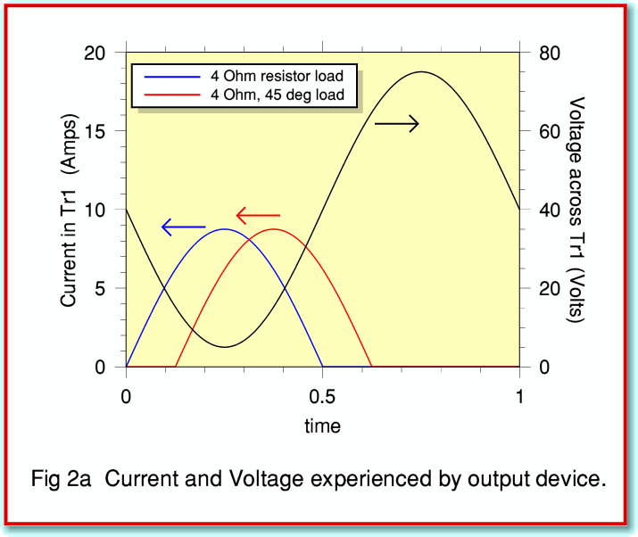
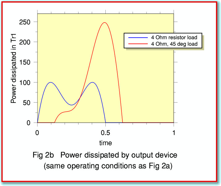
Figures 2a and 2b illustrate Tr1’s situation when we use our amplifier to provide a 70V peak-to-peak sinewave into a load whose impedance is 4 Ohms. Two examples are shown. In one (blue lines) the load is a plain 4 Ohm resistor. The other (red line) also has an impedance whose magnitude of 4 Ohms, but it is a complex load which includes both resistance and inductance. The inductance delays the current variations so they are out of step – i.e. out of phase – with the signal voltage. The presence of the inductance (or capacitance) introduces into the load what engineers call reactance. Here I’ve chosen to arrange that the phase offset is 45 degrees.
Figure 2a shows how the voltages and currents vary during one cycle of the sinewave. (The arrows indicate which scale to use for each line on the graph, with the black line showing the voltage across Tr1.)
Figure 2b shows how the power dissipated by Tr1 varies with time. Note that although the peak power Tr1 has to survive is only about 100 Watts for the 4 Ohm resistive load, it shoots up to around 250 Watts for the complex load! Clearly, the load’s reactance has a dramatic effect. Note that it is assumed that Tr1 only has to pass current when the load current is positive. Negative load currents are handled by Tr2. In general we can expect the transistors to experience similar conditions on average.
Alas, most real-world loudspeakers have reactance. This means that the power amplifier has to work far harder, and be much more rugged than if the load was a simple resistor. To see how bad this can be, look at what happens when we use a loudspeaker whose impedance behaviour is illustrated by Figure 3. This shows two peaks or resonances (blue line) in the magnitude of the speaker impedance. Since the impedance is generally over 4 Ohms it might seem not to be a particularly ‘difficult’ load for a power amplifier to drive. But the problem becomes clear when we also consider the (broken red) line that shows the speaker load’s phase angle. This can be seen to swing over a range of more than ± 40 deg across the audio band.
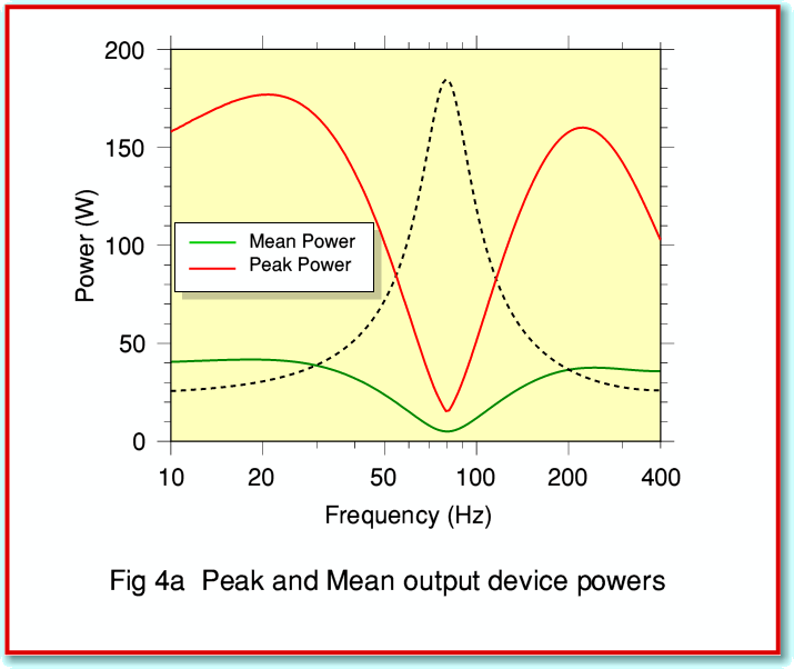
Using this example we can now plot the peak power dissipation our amplifier’s output devices would have to survive at various frequencies if we drive a 70 volt peak-to-peak sinewave into the loudspeaker. We can also plot the mean power level each output device has to dissipate, averaged over each cycle of the sinewave.
The graphs plotted in Figure 4a show how the output device powers vary with frequency when using our loudspeaker load. (The broken line on this graph shows the shape of the speaker’s impedance resonance for the sake of comparison.) For clarity the plot zooms in to view just the low-frequency resonance. By comparison, if the load were a 4 Ohm resistor, the peak device dissipation would be around 100 Watts, and the mean dissipation around 35 Watts.
At resonance, the load impedance is high, and the device dissipations are low. This is what we’d expect since at resonance the load looks like a resistance much larger than 4 Ohms, and so the current level is very low. However away from the resonant frequency the effect of the phase angles in the ‘wings’ of the resonance require the output devices to dissipate quite high peak powers – typically over 50% greater than for a 4 Ohm resistor, even though the impedance has a magnitude above 4 Ohms. From below 10Hz to above 200 Hz, the 80Hz resonance in the load impedance causes the peak dissipation to be well above that of a simple resistive load of similar magnitude!
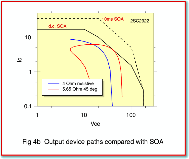
In practice, the designer of a power amplifier will be concerned with what is referred to as the Safe Operating Area (SOA) of the output devices available. A typical plot is shown Figure 4b. In this case I have used the example of the 2SC2922 transistor which has been used in commercial designs – e.g. the Audiolab 8000 series power amplifier. The solid black line representes the limits of the ‘d.c.’ SOA. Provided that the transistor is on a good heatsink whose temperature is 20 Celsius, the device should be able to survive any combination of voltage and current within this area for an indefinite period. Higher temperatures tend to shrink the SOA. Perhaps fortunately, brief excursions to higher levels are permitted, as shown by the 10 millisecond SOA (broken black line).
The blue line plotted on the SOA shows the relationship between device voltage and device current when driving a 4 Ohm resistive load. It can be seen that this is comfortably inside the dc SOA. The red line shows the voltage-current relationship for a 5·6 Ohm, 45 deg, load. Note that even though this draws less current than a 4 Ohm resistor, the line strays right up to the edge of the d.c. SOA. This acts as a warning to the designer who may have to cater for more difficult loads, and allow for the heatsinks to be rather hotter than 20 Celsius!
In fact, each type of gain device the designer may choose will have its own safety limitations, so this isn’t just a matter of the maximum current, voltage, and power. But it can be seen from the above that the choice of loudspeaker can make life much harder for a designer who wants the ampifier to work well, and be reliable. A particular worry is that, in general, the amplifier designer has no idea which loudspeakers each individual customer may choose – including ones the designer had never heard of or weren’t even on sale when he designed the power amplifier!
At the end of all the complications what emerges is a fairly simple set of conclusions which the members of SCAMP have been happy to keep a dark secret. In practice, the amplifier has to have a generous margin of ‘extra’ performance to endure the effects I have described, or there is a risk that it will fail in use. This in turn tends to put up the cost of the amplifier, or cause the designer to wind down the levels of power available into more reasonable loads. It also means that some designers may feel they have to add ‘current limiters’ or other additional circuitry to protect the power amplifier from some speakers. The result is a trade off between extra cost and compexity, a reduction in the signal levels that can be played, and the risk of equipment failing in use.
Up until now, amplifier designers have endured this situation in silence. But maybe it is time for them to rebel and call for action against the scamps who make their life such challenge. Perhaps the time has come for purchasers to also rise up and demand an easing of their load. More power to the music, and down with reactionary forces!
Jim Lesurf
First Published in Hi Fi News, May 2007


