FM sound radio was introduced into the UK during the 1950’s. By the end of that decade the BBC had a network of over a dozen main FM transmitter sites. Although the coverage was limited, almost everyone who was within the covered areas and had a good tuner plus antenna found that the results could sound superb. However during the 1950’s and 1960’s the other exciting new buzzword in HiFi was “stereo”. As a result, the pressure was on broadcasters to find a way to transmit in stereo. Various systems were proposed, but the system that won was the “General Electric / Zenith” system. This was adopted by the BBC, and by other broadcasters around the world and became the established standard for FM stereo radio until the present day.
FM stereo was also a great success. The main complaint at the time was the painfully slow progress the BBC made in expanding the coverage. This meant that many listeners has to wait years before their area was covered by FM in Stereo. Also, in the early years there were only a few hours per week of stereo. Back in the 1960’s many of us used to wait in excited anticipation for the little ‘pilot light’ on the tuner to come on for one of the rare broadcasts!
One of the snags was that the stereo system was a ‘bolt on’ addition to the existing FM broadcasts, and had to be designed so that monophonic FM radios weren’t affected. So the GE-Zenith system had to use a sneaky method to encode the stereo and ‘hide’ it from mono radios. The solution they adopted is illustrated in the diagram.
For mono FM radio, the sounds are given an audio bandwidth of 15kHz. Hence with mono transmissions the broadcast simply FM modulates the radio transmissions with frequencies up to 15 kHz, according to the spectrum of the sounds to be broadcast. When listening to mono on a stereo system the normal procedure is to have the same sound playing in both channels. This therefore simply uses the mono sound sound for both the Left (L) and Right (R) channels. For stereo, the ‘trick’ is to convey the difference between the L and R sounds by modulating an ultrasonic subcarrier at 38 kHz. In practice, this appears as a ‘mirror image’ pair of components either side of 38 kHz. The above diagram represents this with the blue shape representing the audio information for an example of a mono sound, and the red shapes representing stereo (difference) information. The audio signals are said to be multiplexed together before being used to frequency modulate the transmitted VHF.
A mono receiver simply ignores any components above 15 kHz that emerge from the FM demodulator. But a stereo receiver also detects the extra signals above 15 kHz. It then uses a stereo demultiplexer to combine them with the mono and re-create the required stereo[1]. The system can work very well, but adding on the stereo information in this way can lead to problems which often tend to be overlooked...
The largest change (deviation) in the radio frequency that is allowed is ±75 kHz. This is regarded as “100% modulation”. FM radio is generally regarded as being able to deliver low levels of nonlinear distortion. Typically, values in the range from 0·1% to 0·3% THD for a 400Hz mono (L+R) sinewave at the 30% modulation level. For most purposes, these results would be regarded as fine, but as stated they can be misleading.
If you look at relevant material on communications engineering (e.g.[2]), you may notice two things about the analysis of FM. Firstly, if you work out the RF spectrum of an FM signal, you tend to find that – in theory – it isn’t confined to a finite bandwidth! That may seem an odd statement if you aren’t familiar with this area, so let me give a simple example. Figure 2 illustrates the RF spectrum we get if we modulate the frequency of a radio carrier with a sinewave.
For this example the modulation is a 38kHz sinewave which swings the carrier frequency up and down by 45 kHz. Figure 2 shows a whole series of what RF engineers call Sideband Components at frequencies above and below the carrier (shown at 0 kHz). This spectrum is quite different to what we would have obtained with AM. There are also components at other frequencies which extend off the plot on both sides. This means that if we want to communicate even a simple sinewave perfectly using FM we have to use a very wide radio spectrum bandwidth. More importantly, we’d have to prevent anyone else from transmitting in this range when doing so to avoid interference. The result might be only allowing one radio station on air at any time!
The second point is that textbooks tend to steer clear of analysing modulation by anything other than a simple sinewave. This is because it becomes very difficult to calculate the results, and the resulting sideband patterns become very complex. This is particularly true with FM Stereo which – as we saw earlier – uses an ultrasonic subcarrier to convey the stereo information as pairs of signals either side of 38 kHz. As a result, the transmitted spectrum for FM stereo can be quite complicated.
Fortunately, most of the spectral power of an FM wave tends to appear at frequencies near to the carrier. As a result, broadcasters agreed to bandpass filter their FM transmissions. They also have agreed to limit the range of frequency modulation or they will use to just +/- 75 kHz. This then allows each broadcast to occupy a defined radio channel, and we can have a selection of stations. However this agreement comes with a price-tag. It means that the transmitted FM signals have been altered by the filtering process. This subtly changes the details of the signals, and may lead to distortion.
Some FM tuners offer ‘wide’ IF/RF bandwidths. On bench-tests this means they can deliver very low levels of distortion – even for 100% modulation at high frequencies and in stereo. But this relies on the signals from the test generator being directly coupled to the tuner and using a wide RF bandwidth. Alas, broadcasters can’t do this because they are obliged to filter their RF transmissions. As a result, the excellent test-lab results may not apply when listening to real broadcasts, even in ideal reception conditions! Instead we get levels of distortion, produced by the limitations imposed on the actual transmission, but which may not show up in magazine reviews.
To examine this problem I wrote some programs that simulate the FM system, apply an RF bandwidth filter, and then work out the resulting distortions when the signal is demodulated. For the sake of simplicity I looked at stereo L-R difference signals conveyed by modulating the 38kHz ultrasonic subcarrier. This means I ignored any mono sounds, and also omitted to include the 19kHz pilot tone. In practice the pilot tone is necessary for the stereo decoder to work. However the pilot is at a relatively low level. Its presence makes the spectra more complex, but only has a modest effect on the distortion for loud sounds. I also assumed a simple 200 kHz ‘top hat’ shaped RF filter had been imposed by the combination of the broadcaster, and the filtering in the tuner. This filtering is represented in Figure 2 by the pink area within the broken red line. It means that components within 100kHz of the nominal carrier frequency are passed unchanged, but any components outside this range are completely blocked by the filtering. These assumptions make it easier to illustrate clearly what happens.
Figure 3 shows some typical results with a signal of 30 kHz peak deviation. This displays the shapes of the waveforms as they would emerge from the FM detector in your tuner. The blue plots show what we would get with an ideal FM system with no RF bandwidth limitation. The red plots show the effects of finite RF bandwidth. As a result of the way the stereo information is carried we can see that the waveform doesn’t look like a simple sinusoid at 4 kHz. However by comparing the blue and red shapes we can see that the pattern which arrives is very similar to what was intended. As a result, once stereo demodulation is carried out in the tuner, the result should not be significantly distorted. However ±30 kHz modulation is much quieter than the maximum volume of audio possible for FM transmissions.
Figure 4 shows what we get if the stereo signal was louder, and reached 60 kHz peak FM modulation. Now the received (red) waveform looks very different to the intended shape (blue). If we plot the spectra of the waveforms for the encoded stereo we get the results shown on the right of Figure 4. The red bars clearly show distortion components that were not present in the intended signal. It should be quite clear from these results that the RF bandwidth restriction does lead to distortion – particularly for loud stereo sounds.
In practice, the RF filtering is much more complicated that I have assumed. This will change the details, but not the overall tendency to produce distortion of a level similar to that produced by my simplified model.
To make the situation clearer, Figure 5 shows how the distortion level for a 4 kHz stereo difference tone will vary with the volume level of the audible tone. This shows that the amount of distortion will be negligible for quiet sounds, but will rise dramatically as we approach the maximum volume levels permitted for broadcast FM. Fortunately, the problem is less serious for the mono part of the signal. Hence mono, or stereo with only low levels of stereo signals, may sound undistorted. But loud passages of music in stereo may be subject to rather more distortion than we’d expect if we simply rely on test-bench figures which don’t take the real-world RF bandwidth limit into account!
The modulation required for real-world sound transmissions using FM radio are rather more complex that the examples shown above. Up until now I have ignored the effect of the 19kHz pilot tone, and assumed an idealised ‘top hat’ shape for the effective RF bandwidth shape. In practice the effect of the filtering is harder to analyse in detail, and the presence of a 19kHz pilot will make the spectral shapes more complex.
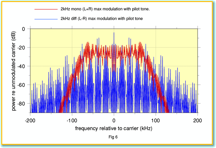
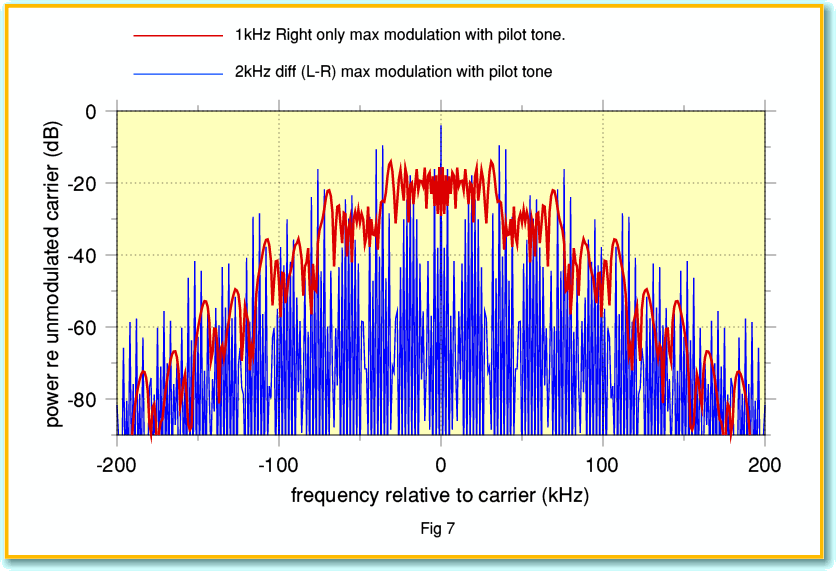
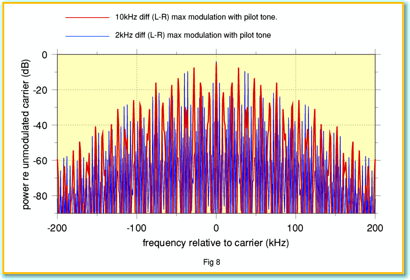
We can illustrate this with the following examples. For these I used a more realistic modulation which includes details like the 19kHz ‘pilot tone’. I’ve also included some examples of mono or single channel modulation sounds for the sake of comparison.
Figure 6 shows the RF spectra we would get if we transmit a signal FM modulated at maximum deviation using a 2kHz sinusoid as the audio waveform. The red line shows a ‘mono’ (L+R) audio signal. The blue line shows a ‘difference’ (L-R) audio signal. We can see from the comparison that the L-R case has much more of its power at frequencies greater than 100 kHz from the nominal carrier. Hence any filtering of the RF during transmission or reception will have more impact on the stereo part of the audio.
Figure 7 shows the transmission spectra for a 1 kHz right-channel only audio signal (red) and compares this with a 2kHz L-R audio signal. As you can see, these have fairly similar overall spreads of power despite having detailed differences. This result is because a right-channel-only or left-channel-only audio signal is transmitted by using a combination of a L+R and L-R signals. So the result has the kind of spread in the spectrum which resembles the L-R case which gives rise to the power at frequencies well away from the carrier.
Finally, Figure 8 shows an extreme case where the red line is the spectrum of a 10kHz L-R audio signal. It can be seen that although this gives more power beyond +/-100kHz than the 2kHz example (blue line) the difference isn’t as great as you might expect. This is because L-R modulation is already spread across a wide spectral range by the use of a 38kHz subcarrier.
The above confirms that the stereo difference portion of the FM broadcast requires a wide bandwidth. The precise result will depend on the circumstances, be we can expect much higher distortion for loud stereo difference audio than for monophonic sounds. The above examples shown in Figs 5-7 are all for cases where the audio is as loud as can be transmitted. Fortunately, at lower sound levels the spread is reduced, so any distortions caused by limited bandwidth will also be reduced.
Bear in mind that the argument completely ignores various real-world effects like tuner imperfections or multipath reception which may alter the results, and might to lead to higher levels of distortion than shown here! The results should therefore be regarded as a guide to the ‘best performance’ one can generally expect, but that a given tuner may perform slightly differently – alas often worse – than shown here.
The good news is that the BBC R3 engineers are well aware that it makes sense to keep the sound modulation levels well below the peaks that are officially allowed for broadcasters. Unfortunately, with many commercial stations the main concern is to get the maximum ‘impact’ possible. They are less concerned with avoiding this distortion. Indeed, commercial stations often employ aggressive amounts of upward level compression! This means sounds that can be significantly altered by level compression, tonal balance changes... and peak distortion on FM.
The drawback of low modulation level is to move the sound of the music down towards the background noise. This is one of the factors that then tempts the BBC to employ some level-compression on R3 FM, in order to avoid people switching off because they find that the music is drowned by distracting levels of noise during the quieter passages...
For many of the commercial stations the sound on both FM and DAB may be dominated by level-compression, and then we are given a choice between relatively high levels of nonlinear distortion on FM versus bitrate limitations on DAB. An unenviable choice! In practice, of course, various other factors I’ve not considered here will also affect the results.
Unfortunately, it is almost impossible at present to give reliable technical information on many DAB tuners regarding various points that may affect the sound they produce in a given situation. I have a great deal of data on the Yamaha CT7000 FM tuner I’ve used for my own comparisons. But despite repeated attempts on my part, Pure did not provide me with answers to the technical questions I tried asking them about their 701ES tuner.
Of course, if the station you like is also on DTTV, then you may prefer that as it avoids the problem I’ve considered in this article, and may use a higher bitrate than on DAB! However, given the points I have explained in this article, and some others I have ignored like multipath and ignition interference, I’d say that FM isn’t a one-way bet as favourite!
[1] http://www.st-andrews.ac.uk/~www_pa/Scots_Guide/RadCom/part21/page1.html
[2] http://www.st-andrews.ac.uk/~www_pa/Scots_Guide/RadCom/part12/page1.html


