I’ve not yet found a computer whose inbuilt analogue audio output seemed really satisfactory to me. In general I therefore use either USB or optical SPDIF outputs and a decent external DAC like the Cambridge Audio DACMagic. However I’ve recently started wanting to use a pair of headphones with my (Xubuntu+ROX) laptop. As a result I had a look around to see what might be available that was portable and could accept optical SPDIF. I did find a variety of headphone DACs on sale. But I must admit they did seem expensive to me when considering ones with rechargeable batteries and a volume control. So this set me wondering, could I devise and build a fairly simple ‘home brew’ portable headphone DAC?... Having started looking into this I then started to wonder if I could come up with a design that was inexpensive and so easy that anyone willing to use a soldering iron and drill some holes in a box could make one for themself. i.e. the basis of a ‘kit’ which didn’t require the maker to have much previous experience or skill in electronics.
One of the first things that occurred to me was that headphones usually only need a tiny amount of signal power. Unfortunately their impedance properties aren’t really suited to being driven directly by the output from a normal domestic audio DAC. Typically, the HiFi DACs you buy produce about 2 Volts rms when supplied with a 0dBFS (i.e. max level) digital input. That seems ample at first glance because many headphones will output 100dB or more when driven with 1 Volt! The snag is that conventional DACs are designed to drive a load resistance far higher than the 32 Ohms typical of a pair of headphones. So although most DACs can provide the voltage, they can’t supply enough current.
Thinking about this made me realise that the real problem here was an impedance mismatch. These days electronics designers almost automatically ‘solve’ this kind of problem by designing in an amplifier stage that can supply the required extra current. However that would complicate the DIY, so my mind drifted back to the ways of earlier days when the first reaction of the engineer would be... how about using a signal transformer? Thumbing though some component catalogues I found what looked like a possible solution, illustrated in the diagram below.
Figure 1 Schematic of circuit
This shows the basis of the design. It uses a pair of audio signal transformers to ‘step down’ the voltages from the DAC. In the process they also ‘step up’ the amount of current available to the headphones. No amplifiers needed, just a pair of small transformers.
Experiments and choosing the components.
Looking in the CPC catalogue (www.cpc.co.uk) I found a small inexpensive DAC made by a company called CYP. It cost about 35 pounds and is powered by a small ‘wall wart” 5Vdc PSU that you get with the DAC. This was cheap enough for me to decide to just buy one, experiment with it, and find out what it could do. When I tested it I found that it would output 1V rms when driven with a 0dBFS SPDIF input. And it would quite happily drive 1 kOhm loads with no sign of any clipping or increase in distortion that might indicate it was struggling. CPC also sell various small audio signal transformers. So I bought some of these and experimented with them. Here I will just concentrate on the Neutrik ‘NTE4’ transformer which has a 4:1 turns ratio because that proved to work OK for my purposes.
In principle a transformer with a 4:1 turns ratio could step down the output voltage by a factor of 4 whilst increasing the available current by the same amount. This means it would make a 32 Ohm set of headphones look to the DAC as like a 16 x 32 = 512 Ohms. This still seems a bit too low for a simple DAC that wasn’t designed to supply much signal current. However real transformers have various imperfections, and they sometime can actually help! The main factor here is that a physically small audio signal transformer will have windings with fairly high resistances.
Figure 2 Audio Transformers used
When I measured them at dc the CPC NTE4 transformer windings had resistances of 228 Ohms for the red-black wires and 56 Ohms for the white-yellow wires. The higher resistance indicated which pair of wires connected to the ‘high’ voltage and impedance side of the transformer since this implies more turns of wire (and perhaps also thinner wire due to the lower current that would need to be carried). Figure 2 shows a schematic diagram of the NTE4, including its ‘internal’ winding resistances.
In addition to dissipating some of the signal power these internal wiring resistances also affect the impedances presented by the transformer. In effect even if one side were shorted (zero Ohms) the other side would appear to have a non-zero impedance simply due to these internal resistances! Since the impedance transformation ratio is the square of the voltage ratio we can say that
- For the ‘low’ (white-yellow) side the transformer will always add 56 + (228/16) Ohms to the transformed impedance. i.e. anything connected to this side will see an impedance that is never less than 70 Ohms. So if, for the sake of example, we assume that a source connected to the other side has a source impedance of 100 Ohms then the apparent source seen on the ‘low’ side will be 70 plus 100/16 Ohms. i.e. about 76 Ohms. This means that with a low impedance source driving the ‘high’ side, the source impedance apparent on the ‘low’ side is essentially determined by the transformer resistances
- In a similar way for the ‘high’ side the minimum impedance presented by the transformer between the red and black wires will be 228 + 56 x 16 = 1,124 Ohms. i.e. even if we short together the yellow and white wires a source driving the ‘high’ side will see an impedance of just over 1 kOhm!
Since the DAC I had chosen has been able to happily drive a 1 kOhms load the presence of the resistances of the transformer windings meant it would safely drive a low headphone resistance via the transformer.
The HeadDAC and its performance.
The design I settled on using consists of three parts. The first is the DAC. The second is a convertor box which contains the signal transformers. The final part is a replacement for the mains psu since I wanted the system to be portable.
Figure 3 The convertor box
Figure 3 shows the circuit for the convertor box. I decided to include a volume control as this makes the HeadDAC easier to use – particularly if the source supplying spdif to the DAC does not have its own digital volume control! For the volume pot I used 4k7 dual-gang log pot. For simplicity and low cost I chose an Omega pot. I built the circuit into a small die-cast metal box and used phono/RCA sockets for the inputs and outputs. This was just for convenience as I had the box and connectors to hand. Also phonos made connecting test equipment easier. In practice you can use any convenient (preferable metal) box and use a standard headphone socket for the outputs. Ignoring the box, internal wires, and connectors, the basic parts list for the above was
- CYP AU-D3 DAC [CPC DCT-3 part number AV18219 cost 34·42 UK Pounds]
- Two Audio Transformers [CPC NTE4 part number LS01463 cost 7·48 UK Pounds each]
- Volume pot [CPC Omega dual log 4k7 part number RE04439 cost 1·79 UK Pounds]
For my initial tests I used the coaxial SPDIF output from a Quad 67 CD player and various test discs that I know provide good quality test waveforms. With no loading on the headphone outputs, and using the supplied mains ‘wall wart’ PSU for the AU-D3 I obtained an output from the convertor of 0·235 Vrms when the volume control was set to maximum level. When loaded with a 100 Ohm resistor on each of the outputs this fell to around 0·132 Vrms. This indicated that the convertor had an output impedance of around 80 Ohms when the volume control was at maximum. (From above that implies the AU-D3 has an output impedance of around 200 Ohms.) The response was essentially flat across the audio band with the -1dB points at around 20Hz and 20kHz.
The following table of values shows how the level of harmonic distortion varied with signal frequency, level, and choice of load. In all cases shown the AU-D3 was driven with a 0dBFS sinwave to give its maximum output of 1 Vrms. The columns where the level is ‘Max’ represent the volume control being set to give maximum output. The ‘-6dB’ column was with the volume control adjusted to reduce the output by 6dB from maximum.
| Load
|
33 Ohms
|
33 Ohms
|
100 Ohms
|
open
|
| Level
|
Max
|
-6dB
|
Max
|
Max
|
| Frequency
|
THD
|
THD
|
THD
|
THD
|
| 200 Hz
|
0·07%
|
0·02%
|
0·01%
|
0·01%
|
| 100 Hz
|
0·07%
|
0·03%
|
0·03%
|
0·03%
|
| 50 Hz
|
0·12%
|
0·10%
|
0·14%
|
0·11%
|
| 31·5 Hz
|
0·36%
|
0·26%
|
0·52%
|
0·57%
|
| 20 Hz
|
1·33%
|
0·76%
|
2·87%
|
34% (!)
|
The two columns with a green background were with the headphone output loaded with a 33 Ohm resistance. This gives a loading similar to the typical nominal impedance of ‘32 Ohm’ headphones, so probably represents the values likely to occur with headphones for the given test signal and volume.
From these columns you can see that for frequencies above 50Hz we can expect the distortion to be around 0·1% or less. And for frequencies above 100 Hz the distortion tends to be well below 0·1% – particulary when the signal level is below the maximum. The relatively high distortion at 20Hz when the signal is at maximum level is due to the small transformers.
The column with a blue background is for a 100 Ohm resistive load. The red column are the results when no specific load was connected. (This means the actual load was somewhere above 10 kOhms due to the measurement equipment, plus some cable capacitance) Although useful for diagnostic purposes the red column isn't what you'd expect when headphones are connected.
From the values we can expect that the distortion levels should be low enough not to be a problem when using typical domestic headphones provided the music doesn’t contain high levels at frequencies below about 30Hz. So although small and inexpensive, the transformers seem to me to be adequate for reasonable listening. But this does depend on your taste in music, how loud you want the music, and your choice of headphones! Better transformers with improved LF signal capability and lower winding resistances could be expected to reduce the LF distortion and increase the signal levels available. i.e. a louder cleaner output when the music has a lot of LF.
It may be useful here to point out one effect (illustrated by the red column in the table)I noticed whilst experimenting and testing. This is that if you have no output loads the transformers may well saturate with loud low-frequency signals. So, for example, a 20 Hz sinewave at 0dBFS will be seriously distorted. However with output loads of a few hundred Ohms or less this effect disappears when driving the transformers with the AU-D3. Hence this isn’t a problem in practice when using headphones with impedances of a few hundred Ohms or less – i.e. essentially all normal domestic headphones.
I then adjusted the volume control to give a reduction in level of about 3dB when the output was unloaded. This caused the 100 Ohm loaded output to fall by more like 8dB. This was because changing the volume pot setting alters the series resistance. In this situation the output impedance rose from 80 Ohms to about 140 Ohms. Since I was using a 4k7 volume pot the ‘worst case’ for this would be when the volume reduction with no loading is 6dB. That can be expected to increase the output resistance by a quarter of the pot value (i.e. around 1200 Ohms) which scaled down by a factor of 16 by the transformer comes out to an extra 73 Ohms. Hence the worst case should be an output impedance for the convertor of about 80 + 73 = 153 Ohms.
A smaller value for the volume pot (say 2k2) would reduce this effect, but slightly increase the demands placed on the DAC. During tests and later listening I decided that I was happy with the 4k7 pot. But if you build a similar system you might find you prefer a different value for the pot or perhave even to omit the volume pot entirely and use a digital level adjustment prior to the DAC!
Most modern headphones have a quoted impedance of around 32 Ohms. As with loudspeakers being called ‘8 Ohm’ such values should be regarded with some caution as the reality may be an impedance that varies wildly with frequency. For my tests I tried a few different headphones and was surprised to find that most were reasonably close to 32 Ohms, although pair were just 18 Ohms. After some comparisons I settled on using a pair of Sennheiser EH350 headphones with the HeadDAC. These have a claimed sensitivity of 115dB for 1 Vrms input which implies that 0dBFS with the HeadDAC would drive them to around the 90dB level. That isn’t stunningly loud in Death Metal terms, but I found it to be more than adequate for me when listening. Indeed, I found I usually set the volume well below max for rock/pop/jazz material and only wound it up when listening to Radio 3 or classical music that had a wide dynamic range.
Initial experiments and checks were done using the ‘wall wart’ PSU supplied with the AU-D3. However since I wanted a portable HeadDAC I moved on to trying out various types of battery supply. Using batteries frees you from some of the potential problems with mains power, like mains-conveyed interference and buzz due to ripple. However batteries have two drawbacks. One is that they run down and then need to be replaced – or recharged if using rechargeable types. The other is that the dc voltage they provide tends to slowly reduce as they are used. I could have decided to make a stabiliser circuit, but that would have made the HeadDAC more complicated. So instead I did some tests to see the effects of using various battery voltages.
A set of four AA sized Duracell Alkali cells in series gave a voltage of about 6 Volts dc when new. I tried using these to power the AU-D3 for about 15 mins and the it worked without any problems. However the AU-D3 mains PSU nominally supplies 5 Vdc, so I was worried that long term use of 6 Vdc might cause damage. Hence I decided to avoid using the Alkali cells. At the other extreme I tried four old AA cells that were almost worn out. These could only deliver 2 Vdc when powering the AU-D3. But despite this being way below the 5 Vdc that is nominally required the DAC worked OK! The output level it produced dropped by about 5dB compared with using 5Vdc. But even with 0dBFS digital signals there was no sign of clipping or increased distortion. This was good news as it meant that when used with a battery power supply the effect of the batteries discharging or wearing out was simply that the volume level reduced.
I then tried using four NiMH rechargeable AA cells in series. The cells had recently been fully charged. Immediately after charging they also gave about 6 Vdc. But left to cool down (they become warm during charging) this dropped to 5·5Vdc. Using these, the AU-D3 and convertor gave essentially the same performance as with the mains PSU. Since the DAC works satisfactorily with a supply down as low as 2Vdc these rechargables can be used until almost drained. Then recharged for later re-use. I spent some hours listening to music using the HeadDAC with these NiMH cells to satisfy myself that the 5·5 Vdc maximum was fine. So far, the DAC has continued to work without any problems. Hence I have decided to go on using the NiMH cells. To use the AA cells I bought one more component from CPC. This is a 4 AA cell holder with wire leads [CPC part number BT03711 price 57 pence]. The dc connector required for the AU-D3 is a standard type with an outer diameter of 5.5mm, an inner diameter of 2.1mm, and a length of 9.5mm. (If you use NiMH or NiCad cells you will also obviously need a suitable recharger.)
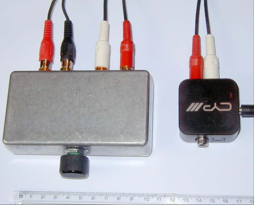
The above photo shows an external view of the adaptor box (on the left) that contains the volume pot and the two transformers. On the right the photo shows the AU-D3 with its power plug on entering from the right. This shows how small the AU-D3 actually is! The coax and optical SPDIF inputs to the AU-D3 are on the side closest to the ruler that shows the scale of the photo.
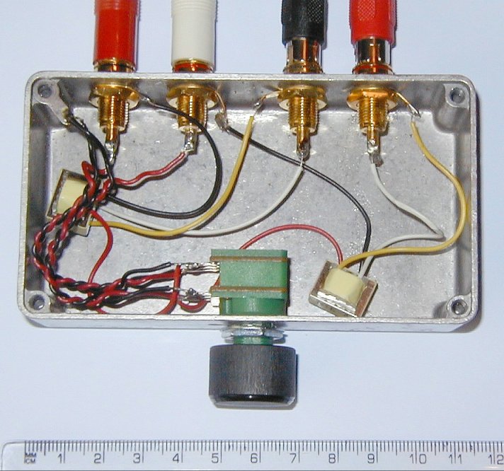
The above shows an internal view of the adaptor box. The 4k7 volume pot is green, and the two NTE4 transformers are a cream/yellow colour. Looking at the two photos you can see that it would be quite easy to fit the entire HeadDAC with a battery supply into one small box. I may do that at some point, but at present I’m happy with a set of boxes as it makes experiments easy. The convertor box also may make a useful basis for experiments with modified circuits to produce tailored crosstalk, etc, to see the effects on the headphone experience.
Listening to music I am quite pleased with the results. Although I initially wanted the HeadDAC for tasks like listening to files on my laptop whilst editing or analysing them, I found I also enjoyed using the HeadDAC with my main audio system. It had been some years since I’d used headphones for serious listening, so rediscovering enjoying using them was fun. There may well be ‘better’ transformers and volume pots, and if you wish to use different headphones you may find alternative components give optimum results. However the only tweak I am personally tempted to add is a balance control!
Jim Lesurf
26th Jul 2010