2·4 Class AB
The Class AB arrangement can be seen to be very similar to the Class B circuit. In the example shown it just has an extra pair of diodes. The change these make is, however, quite marked. We now find that – when there is no output – we have a potential difference of about  between the emitters of the two transistors. As a consequence there will be a Quiescent Current of
flowing through both transistors when the output is zero. For small output signals that require output currents in the range  both transistors will conduct and act as a double ended Class A arrangement. For larger signals, one transistor will become non-conducting and the other will supply the current required by the load. Hence for large signals the circuit behaves like a Class B amplifier. This mixed behaviour has caused this approach to be called Class AB.
When driving sinewaves into a load,  , this means we have a quasi-Class A system up to an rms voltage and output power of
If we take the same audio example as before ( ), assume a typical diode/base-emitter drop of 0·5V, and chose small value emitter resistors of
  this leads to a maximum ‘Class A’ power level of 20 Watts. The Quiescent Current will be around 1 Amp, so with
  power rails this system would still dissipate around 50 Watts in total. In this case the system is more like Class A than Class B. We do, however have some control over the circuit and can adjust the bias current level.
The obvious way to change the bias current is to choose a different value for  . Choosing a larger value will reduce
  and
and  whilst still preserving a region of Class A behaviour which can be large enough to avoid the Crossover and imperfection problems mentioned earlier. However if we make
  too large they will ‘get in the way’ as all the current destined for the load must pass though these emitter resistors. Most practical Class AB systems therefore use a different approach. The most common tends to be to replace the diodes with an arrangement often called a ‘rubber diode’ or ‘rubber Zener’.
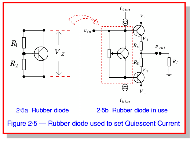
Figure 2·5a shows the basic ‘rubber zener’ arrangement. Looking at this we can see that it consists of a pair of resistors and a transistor. The resistors are connected together in series to make a potential divider which feeds a voltage to the base of the transistor. However the transistor can ‘shunt’ away any current applied and control the potential difference appearing across the pair of resistors. The arrangement therefore settles into a state controlled by the fact that the base-emitter junction of the transistor is like a diode and the transistor conducts when the base-emitter voltage,  , is approximately 0·5 V. Since
  is also the voltage across
  we can expect that
provided that the base current is small enough compared to the currents in the two resistors to be ignored. The above just comes from the normal action of a potential divider. However since in this case the transistor is involved it will act to adjust  to keep
  at about 0·5V. The result is therefore that we can set the voltage
This means we can choose whatever voltage value,  , we require by selecting an appropriate pair of resistors. In a real power amplifier the pair of fixed resistors is often replaced by a potentiometer and the circuit in use looks as shown in Figure 2·5b. The Quiescent current can now be adjusted and set to whatever value gives the best result since we can now alter
  and hence the potential difference between the emitters of the output transistors. In practice the optimum value will depend upon the amplifier and its use. Values below 1mA are common in op-amp IC’s, whereas high-power audio amps may have
  values up to 100mA or more.
Class AB arrangements are probably the most commonly employed system for power amplifier output sections, although ‘Pure’ Class A is often used for low current/voltage applications where the poor power efficiency isn’t a problem. Although we won’t consider there here, it is worth noting that there are actually a number of other arrangements and Classes of amplifier which are used. For example, Class ‘C’ and Class ‘E’ which tend to use clipped or pulsed versions of the signal.
In linear audio amplifiers the most well known alternative is the ‘Current Dumping’ arrangement developed by QUAD (Acoustical Manufacturing) during the 1970’s. This combines a small Class A amplifier and a pair of ‘Dumping’ devices. The Dumping devices just supply wadges of current and power when required, but carry no Quiescent Current so they are highly power efficient, but prone to distortion. The accompanying Class A amplifier is arranged to ’correct’ the errors and distortions produced by the Dumping devices. In effect this means it just has to ‘fill in the gaps’ so only has to provide a relatively small current. Hence the Quiescent level required by the Class A ‘fill in’ amplifier can be small, thus avoiding a poor overall efficiency.
Summary
You should now be aware of of the basic building blocks that appear in Power Amplifiers. That Class A amplifiers employ a high Quiescent Current (sometimes called bias current or standing current) large enough that the transistor currents are large even when the output signal level is small. It should be clear that the power efficiency of Class A amplifiers is therefore poor, but they can offer good signal performance due to avoiding problems with effects due to low-current level nonlinearities causing Distortion. You should now also see why a Double Ended output is more efficient than a Single Ended design. You should also know that Class B has a very low (perhaps zero) Quiescent Current, and hence low standing power dissipation and optimum power efficiency. However it should be clear that in practice Class B may suffer from problems when handling low-level signals and hence Class AB, with its small but controlled Quiescent Current is often the preferred solution in practice. It should also be clear how we can employ something like a Rubber Zener to set the optimum Quiescent Current and power dissipation for a given task.