Developing the Armstrong 730 Pre Amplifier
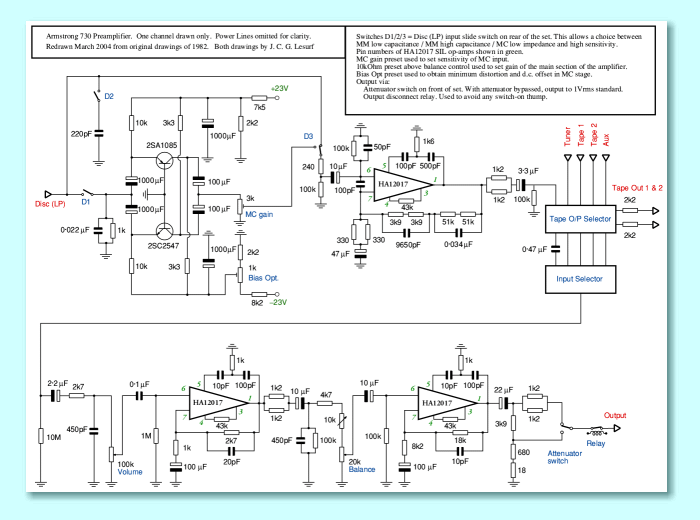
In order to match the high performance of the 732 power amplifier, the 730 pre-amp also had to meet a demanding set of specifications as well as sound excellent in use. Various methods and types of design were examined during the development process. In the end, the chosen design was unconventional for its time in various ways as it was felt that these gave performance advantages. The image shown below is a small picture of the circuit diagram for the 730. Click on the image if you want to see a larger copy that shows the details and component values more clearly.
Note that the above diagram only shows the electronics for one channel, and omits the power supply arrangements.
The main technical requirements were:
- Low noise and distortion levels.
- Flat frequency response across the audio band.
- Ability to deliver output levels up to over 10 V rms without clipping.
- Work well with both MM and MC cartridges for LP replay.
- Ability to drive low impedance loads.
The main choice that had to be made was between using 'discrete devices' (e.g. individual transistors) or integrated circuits for the gain sections of the main sections of the preamplifier. Many people at the time (and since) have felt that designs based upon individual transistors can give better results than the use of ICs. Whereas other people feel that suitable ICs can provide excellent performance. Having experimented with various examples of each approach it was decided that the best sonic and measured results could be obtained using an IC, but using a type that - so far as I know - has not been used in the same way in any other commercial design.
The IC chosen for the gain blocks in the 730 pre-amp was the Hitachi 12017. This was developed by Hitachi for use as an RIAA (LP) amplifier to accept inputs from moving-magnet cartriges. However the specifications showed that it had - for the period - an outstanding combination of low noise, low distortion, wide bandwidth, and high output level capability.
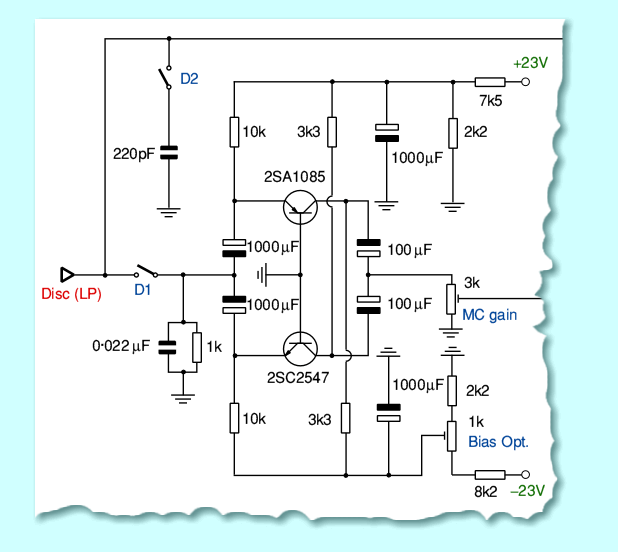
Although ICs were used in the rest of the signal path, the moving coil input required an ultra-low-noise design that would work with low impedance sources. For this task small toroidal transformers were initially considered. These had the advantage of being inherently low noise as no active devices would then have been required for the step-up from MC to MM signal levels. However it was decided that although excellent in many ways, the transformers did have some disadvantages. For example they tended to pick up hum from the environment even when shielded, and despite their toroidal shape.
The MC stage finally chosen is shown above. This is a balanced common-base design which was based upon a design that was popular at the time. For example, a similar design was used by Orthophon in one of their MC preamplifiers that was very highly regarded at that time. For the 730 the design was altered to provided a higher headroom level, and slightly better noise and distortion performance.
Having chosen to use ICs as the gain stages in the RIAA and buffering sections of the preamplifier work on the power supply (PSU) also initially focussed on considering IC-based voltage stabilisers. However although these tended to give very ‘rigid’ control over the long-term voltage levels of the power rails they also tended to inject noticeable amounts of noise, particularly at high frequencies. After a lot of work it was decided that the precise long-term rail voltages did not matter very much provided the rails were very low in noise and absorbed any interference that tried to couple from one stage to another along the power lines. Hence it was decided that better performance could be obtained using a power smoothing circuit that avoided ICs.
The image above shows the 730 PSU. You can get a larger version by clicking on the image shown above. The circuit uses Zener diodes to set the basic rail voltage levels. The Zener-derived voltages are then passed through a pair of RC time-constants. These serve two purposes. Firstly the time-constants suppress any high frequency noise from the Zeners. Secondly, the capacitors then serve as the basis for using a pair of bipolar transistors as capacity-multiplier circuits. The result is power lines with very low levels of noise, and which tend to absorb any signal-induced current variations. Having derived these rails, the voltages are passed through a set of additional individual RC time-constants for each power pin of each IC. The result is to ensure very low levels of noise, crosstalk, and distortion. It also helps ensure the pre-amp has a high degree of immunity to any clicks and pops from the mains supply.
The PSU circuit diagram also shows the circuit used to operate a relay that provided a turn-on delay for a few seconds. This avoided any switch on ‘thump’. A similar circuit was employed in the 732 power amplifier. These were included as Armstrong at the time wanted to avoid any thumps at switch-on. However as is often the case these relays tend to degradewith time. Hence after 20-odd years of use my advice if you have a 730/732 is to bypass the relay - particularly if you find the sound is intermittent. The long-term unreliability of these relays is the only systematic fault I am aware of that time has shown up with the 730/732 amplifiers.

Content and pages maintained by: Jim Lesurf
using HTMLEdit and TechWriter on a StrongARM powered RISCOS machine.

