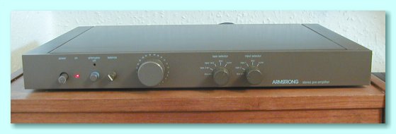
The Armstrong 730 Pre Amplifier
The design brief for the 730 Preamp matched that for the 732 Power amplifier. The unit should enable the user to select and control the signal level whilst preserving the waveforms as accurately as possible. This meant a wide, flat frequency and phase response, ultra-low distortion, high overload levels, low noise, etc.
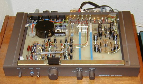
The above picture shows a view looking down into a 730 with the lid removed. You can see that there is just one large circuit board that fills the full width and depth of the case. The ‘disc’ (i.e. LP) sections are near the back of the box on the right. The power supply is at the back on the left, and the sections towards the front are signal buffers. The selector switches are towards the back of the circuit board, located in between the disc amplifiers and the power supply. These are linked to the switch controls on the front panel via a pair of flexible flat encapsulated mechanical sliders. These allow the switching to be located in the best location to keep the electronic tracks short, and away from the output stages, yet still have the controls conveniently placed on the front of the box.
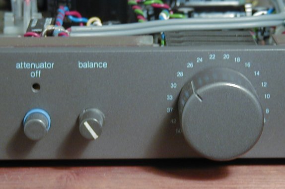
The quality of the controls used for the 730 were superlative. The volume control was a thick-film stepped attenuator. This used laser-trimmed resistors located between hard-gold ‘lands’ as contacts. The control had a ‘detent’ mechanism to allow the volume to be stepped from setting to setting. The values printed around the control show the attenuation settings in decibels. The values shown were accurate to better than 0·25 decibels.
This form of control is much more expensive than a standard continuous track volume potentiometer. Its main advantages are:
- Accuracy. The resistors used are laser trimmed. The units used had a rated balance accuracy and attenuation level of better than 0·5 dB. In practice the units supplied usually showed an balance accuracy of around 0·1 dB, and an attenuation precision of 0·25dB.
- Reliability. Since the contacts were metal to metal the control does not suffer from any of the problems of metal to resistor contacts scraping over a potentiomer surface.
- Control. In principle similar stepped behaviour can be obtained using a multiway switch and a set of component resistors. However the use of film resistors meant that the contact could slide over the actual resistors. This meant that there was no possibility of problems with ‘break before make’ and intermediate volume settings could be chosen if required by deliberately adjusting the control to sit midway between detent clickstops.
The level of control and performance was such that the 730 proved useful for laboratory and test use where repeatability and precision are vital. It also meant the unit was useful when comparing other items since it allowed precise control over test conditions. In use in a hi-fi system the preamp proved to be highly transparent.
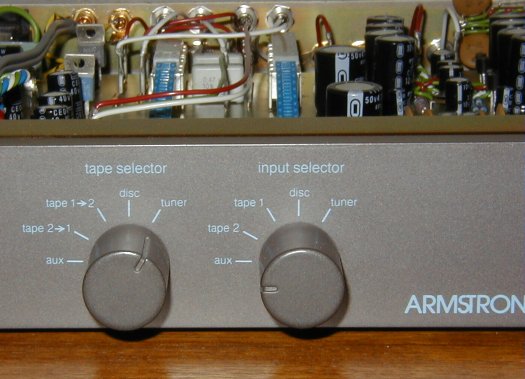
For flexibility, the input and tape selectors (two tape inputs and outputs were included) were via a pair of similar switches. This meant that the unit could be used to listen to one source whilst another was being recorded. The level of crosstalk and breakthrough was low enough for this to be possible without any unwanted audible effects. The units went into production before CD was established. Hence the labels on the switches do not mention CD! However the unit was designed with CD in mind. The headroom and bandwidth were designed to cope with CD sources, and it was intended that the ‘aux’ position on the switches would be renamed ‘CD’ in due course.

Content and pages maintained by: Jim Lesurf
using HTMLEdit and TechWriter on a StrongARM powered RISCOS machine.