Frequently Asked Questions & topics
What inputs and output does the equipment have? What are the sensitivities, impedances, etc? The image below shows the layout of the main inputs and outputs on the back of an amplifier or receiver.
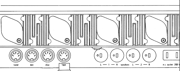
It shows a view looking at the rear on a 621 amplifier. The back of a 625 or 626 receiver looks the same except that the tuner input is omitted for obvious reasons.
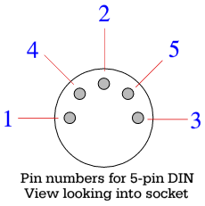 All the inputs are via 5-pin DIN sockets, so you may require a DIN to phono adaptor. The pin numbers are normally marked on any plug you use. For each 5-pin socket the upper (central) pin is the earth/ground connection and is pin 2. In each case pin 3 is the Left-hand channel input and pin 5 is the Right-hand channel input. On the tape socket, pin 1 is the Left-channel output for the tape recorder and pin 4 is the Right-hand channel output for the tape recorder. On some later models the tape outputs are also present on the same numbered pins of the aux socket, but are fed via resistors to act as the old DIN standard current-source outputs. The sensitivity, input impedance, and overload level of each input is as shown in the table below.
| inputs | tuner | aux | disc1 | disc2 | tape
|
| sensitivity (mV)
| 120
| 120
| 3.0
| 6.0
| 250
|
| impedance (kohms)
| 68
| 68
| 47
| 47
| 68
|
| Overload at 1 kHz
| 3 V
| 3 V
| 75 mV
| 150 mV
| 7 V
|
Both disc inputs are via the same input socket and the sensitivity can be set via a slide switch that can be found on the underside of the unit. The ‘high’ setting of this switch gives 6 mV sensitivity and an overload value of 150 mV. The ‘low’ setting of the switch gives a sensitivity of 3 mV and overload level of 75 mV. In general it is recommended to use the high setting unless the cartridge has a low output and the result is too quiet. Note that the input is only suitable for moving-magnet cartridges.
There are a pair of preset level pots beside the disc level switch on the underside of the unit. These pots can be used to adjust the level provided at the tape outputs if desired.
The main power amplier outputs are via DIN loudspeaker sockets. Two pairs are provided and the outputs may be controlled via the pair of loudspeaker switches on the front of the unit. The nominal output power available is up to 40 watts continuous per channel into 8 Ohm loads. Note that the amplifier is only rated for loads above 4 Ohms. Hence if you are using two pairs of loudspeakers symultaneously please ensure that they have impedances of at least 8 Ohms. Headphones may be connected via a socket on the front of the amplifier. The signal provided to this socket is attenuated. If you wish to use electrostatic headphones, connect them to the loudspeaker outputs to obtain the full output level. Note that it is recommended to use 2.5 Ohm series resistors with electrostatic headphones to ensure stability, although this usually only matters with early units.
To the right of the loudspeaker outlets there is a flat-pin mains socket. This provides a mains output which is switched by the unit's on/off power switch and can be used to control the power to another item. Just above the location where the mains cable enters the back of the unit there is a screw binding post that is provided for an earth connection from a turntable/arm/cartridge.
I have a 600 range item, but there is no indicator light I can see that tells me when the unit is on. The indicator should be a small bulb behind the “Armstrong” name label at the left hand end of the set. If this name does not light up when you switch on the unit then the bulb will need replacing.
When I play something via the tape input with the ‘monitor’ button tab down the tone controls, etc, don't seem to work. Is this a fault? No. The 600 range circuit was arranged so that the tone controls and filters act upon the signals sent to the tape recorder. This means you can use the 600 to modify signals when recording them. When replaying tape normally (as with other inputs) the signal will once again go through the tone controls unless you press down the monitor tab. However, when the monitor tab is down, the tape input bypasses the tone controls.
When I change the volume I hear crackles or scraping noises from the loudspeakers. What is wrong, and how can I stop this? This occurs due to dirt or corrosion forming on the volume control. Various brands of volume control were used during the life of the 600 series, some more prone to problems than others. A particular problem sometimes occurs due to leakage current through the capacitor that decouples the wiper of the volume pot from the d.c. present at the input to the power amplifier. Over time, the current tarnishes a spot on the track of the pot, causing a ‘dead spot’ that can then cause a crackle as you change the volume.
The simplest way to solve the problem is to clean the tracks of the volume pot with a suitable ‘contact cleaning’ solution. This is available in spray cans from suppliers like Maplin. I would recommend types of cleaner that are designed to leave no residue. To clean the volume pot, proceed as follows:
Disconnect the set from the mains. Remove the lid. This is held by a pair of lever-action clasps which are at the back corners of the lid, inside where the lid overhangs the chassis. Pull the lower end of each lever away from the back of the set until the lid can me moved backwards. Push the lid backwards. Note that the lid is fitted to go under a lip at the front of the set. Once you have pulled the lid back far enough it can be lifted vertically. Note that if it won't lift you may not have moved it back far enough. Do not apply too much force when lifting. Note that on some later sets, one of the levers also has a small screw attachment that prevents the lid being removed until the screw is undone. This was fitted as the UK safety agency did not like sets that were too easy to get into!
Once the lid is removed you should be able to see the pots behind each control. If you are unlucky they are of a closed type which are almost impossible to clean. However if they have an opening you should be able to see the wipers moving inside when you rotate the knob. If they are open, spray in some cleaner whilst turning the control up and down. Do this a few times to “wash and scrub” away any residues on the tracks of the pot. Reassemble, and see if the problem is cured. If not, you may well need a new pot.
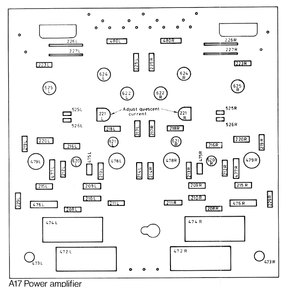
Note that the problem sometimes only occurs during the first 30 seconds or so after an amplifier has been turned on. If so, this is due to the charging currents and it may not be worth cleaning the pot. If the problem persists or returns, it is recommended both to the replace the pot and to change the capacitor on the A17 (shown as component 473) to a new, lower-leakage capacitor.
The above image shows the layout of the components on the A17 power amplifier board and you can see the 473 (L and R) capacitors at the lower corners. In fact, if you are experienced with electronics it is sometimes a good idea to replace all the electrolytic capacitors in an old unit as this may improve the performance. That said, if the unit sounds fine there seems little point in bothering!
I'd like to use the unit to play signals from a CD player. Which input should I use, and how should I connect it? In principle, you can choose to use either the tape or aux inputs. Note that these are via DIN sockets, so you will probably need a DIN-Phono adaptor lead. (These were supplied with the sets when they were new.) CD players can produce signals levels up to 2 volts, which is relatively high compared to the levels from typical sources when the 600 range was in production. This means there is a risk of overloading the input and getting noticeable distortion on loud sounds. This should not arise as the clipping level for the aux input is 3 volts for and tape input is 7 volts. However for signal levels above a volt or two, the inputs may produce more distortion than would be the case at lower input levels.
You are not likely to damage the set by trying either the aux or tape inputs for playing a CD, so the simplest thing is to try either and see if it sounds OK. Ideally, I would recommend using resistors as passive attenuators to reduce the level from CD to around 200mV as this will ensure that overload won't occur and hence minimise any distortion. However you will probably find that the music sounds fine without requiring an attenuator. Note that when the 600 was produced ‘disc’ did not mean CD because Compact Disc was not then available! Hence you can't use the disc input for the output from a CD player. The disc input is meant for the output from a moving magnet cartridge, playing LPs.
A drawback of using the tape input for CD is that the tape DIN socket has the outputs you require if you wish to record signals from the 600. Note that you may be lucky in that some later sets had a second pair of tape outputs provided via the aux DIN socket. With these sets you can choose to use the tape input for CD and treat the aux socket as being for tape. One point to bear in mind, however, is that this second set of tape outputs may be via resistors to accord with the old DIN standard for current source signals. As a result, when used with a conventional tape recorder, the output from the aux socket may sound muffled (loss of high frequencies due to cable capacitance) or at a low level. The existence of this second set of outputs was never advertised. They were just added for those who encountered problems using the european recorders that followed the DIN current-source standard. The tape output signals from the tape socket follow the more usual voltage standard and should be suitable for supplying output to tape recorders, CDR writers, etc.
I have a 621/625/626. However although I hear a ‘thump’ from the loudspeakers when I switch it on, I can't hear anything when I try to play music. It may be that you have the ‘monitor’ button down. If so, the amplifier will ignore all signals except the tape input. Check that this button tab is up if you are trying any inputs other than tape.
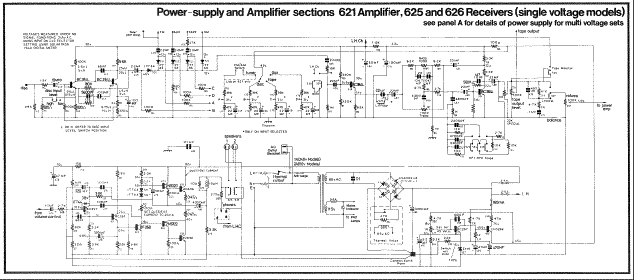
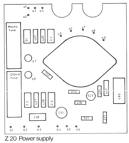
Alternatively, this problem can occur when the fuse that is in the power line to the pre-amplifier fails. These were rated at just about the current that was used, so sometimes fail after some years use. You may need to replace the relevant fuse. This is the 160mA one shown towards the bottom-right of the main diagram. The fuse is located on the Z20 power supply board which is on the UNDERSIDE of the main chassis.
To check that this may be the problem, try connecting a signal source to the tape input and press down the ‘monitor’ button. If you hear music when using the tape monitor input but not when using any other input (including tape with the monitor switch off) it confirms that the power amplifiers and power supply are probably fine, but the control amp is not. The most probably cause of the control amp not working is a failed fuse.
To open the bottom of the set, turn it over. Make sure the set is unplugged from the mains before proceeding. Look at the underside of the set near the back and you should see a series of fasteners that seem like strange screws. They have a pair of parallel 'ridges' on the head of each fastener instead of the slot you would expect in a screw, and are made of black plastic. These are quarter-turn fasteners. Rotate each through a quarter turn. They should now become loose and the plastic base can be removed. Note that it is also held under a lip at the font of the set, so lift it with care.
Look for the Z20 board. It should be labelled, and the layout of components on it should be as shown in the above picture. If the front of the set is towards you, the Z20 board should be near you, on the left. As shown here the control amplifier fuse is to the bottom left of the board. Note that this board will carry mains voltages if the set is on, and may carry high voltages for a while after the set is off due to the time taken for the reservoir capacitor to discharge. Note also that the mains fuse is near the 160mA d.c. fuse, so check you know which is which. Test and/or replace the fuse and reassemble the set. If the set still does not work then the amplifiers themselves may need repair.
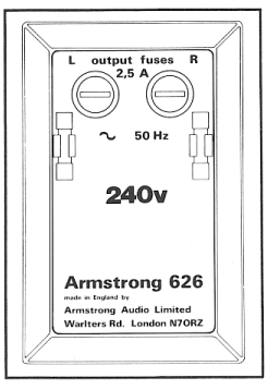 One channel does not work. Is there a fuse that may have blown? Yes. Disconnect the set from the mains and turn it upside down. You will see a recess that looks like the picture shown to the left of this text. There are two circular fuseholders which had a knurled rim and a slot in their tops so they can be unscrewed. These are the powerline d.c. fuses for the power amplifiers. Check and see if either of these fuses has failed. If so, replace it with a 2.5 Amp fuse. If you are lucky the spare fuses will still be held in the clips beside the fuseholders. Note that there may well have been a good reason for the fuse to fail. It may be that the power amplifier is faulty and hence the new fuse will also fail. Is so, the set clearly needs repair. However sometimes the fuse fails due to the output being short circuited. It then is performing the task it was intended to fulfill and protect the amplifier from excessive current demand. Hence the amplifier may work once a new fuse is fitted, provided of course that the short has been removed from the output!

 All the inputs are via 5-pin DIN sockets, so you may require a DIN to phono adaptor. The pin numbers are normally marked on any plug you use. For each 5-pin socket the upper (central) pin is the earth/ground connection and is pin 2. In each case pin 3 is the Left-hand channel input and pin 5 is the Right-hand channel input. On the tape socket, pin 1 is the Left-channel output for the tape recorder and pin 4 is the Right-hand channel output for the tape recorder. On some later models the tape outputs are also present on the same numbered pins of the aux socket, but are fed via resistors to act as the old DIN standard current-source outputs. The sensitivity, input impedance, and overload level of each input is as shown in the table below.
 One channel does not work. Is there a fuse that may have blown? Yes. Disconnect the set from the mains and turn it upside down. You will see a recess that looks like the picture shown to the left of this text. There are two circular fuseholders which had a knurled rim and a slot in their tops so they can be unscrewed. These are the powerline d.c. fuses for the power amplifiers. Check and see if either of these fuses has failed. If so, replace it with a 2.5 Amp fuse. If you are lucky the spare fuses will still be held in the clips beside the fuseholders. Note that there may well have been a good reason for the fuse to fail. It may be that the power amplifier is faulty and hence the new fuse will also fail. Is so, the set clearly needs repair. However sometimes the fuse fails due to the output being short circuited. It then is performing the task it was intended to fulfill and protect the amplifier from excessive current demand. Hence the amplifier may work once a new fuse is fitted, provided of course that the short has been removed from the output!