I was originally planning to continue with the series of articles on ‘resampling’ data. However as I write I don’t have enough data to experiment with so have decided to shelve that for now. I am not sure if that topic is worth following at present so I will wait to see if people are keen to see an improved resampling programme for the Iyonix, etc...
Instead I want to look at a different topic. This one came up as a result of some work I was doing for another magazine. The full results of that will appear elsewhere. Here I want to look at how the analysis was done as it is an example of how we can filter and process sound data for specific purposes. Although I have looked at ‘filtering’ in previous articles, I want to show another approach which might be particularly interesting for anyone familiar with analogue electronics.
The basic requirement I had was to be able to assess what modulation levels occur on real LPs. If you have read earlier articles in this series you will know that the LP records sound information in terms of the ‘wiggles’ in the groove. The nominal reference level at 1 kHz for LP is a groove shape that waggles the tip of the replay stylus with a peak velocity of 5 cm/sec. But what velocities and accelerations turn up on a given LP?
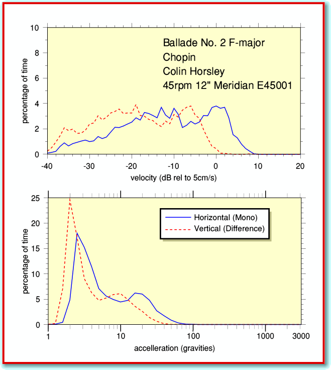
Figure 1
As on previous occasions I have provided the Archive editor (now Jim) with an application to accompany this article. This is called !TrackLPvax and is a copy of the one I used for my analysis. You can use it to examine the contents of your own LPs. I won’t go into all the details of how to make use of it because they’re similar to many of the applications which accompanied earlier articles. (The details are also in a !Help file inside the application.) In some ways this new application is most like !TrackStats. But in this case the output is in terms of the velocities and accelerations found in the LP recording. Figure 1 gives an example of the kind of output !TrackLPvax provides, plotted using !Tau.
Note that the output values in this case are in cm/sec for velocities and ‘gravities’ for the accelerations. However these values will only be correct if you made the recording which is being examined with your recording gain set so that a 1 kHz RIAA 0dB tone on the LP gives a result at -15dB when analysed with TrackStats. This means you would first have to use TrackStats to check the recordings and adjust the gain (or use !TrackGain) to ensure this is so.
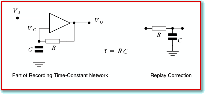
TrackLPvax is more complex than TrackStats because it has to reprocess the sound data in the recording. This is because it has to ‘undo’ the effects of the RIAA preamplifier in your hifi system. The amplifier doesn’t just make the signal bigger. It boosts the low frequency components compared with the higher frequencies in accord with the RIAA curve which I discussed in an earlier article. In order to assess the velocities, etc, the application has to take this into account. To explain this in more detail I am going to use some simple electronics circuit diagrams as these will help those who can read them to make sense of what follows. However I hope the general idea will be clear even if you are unfamiliar with the circuit diagrams.
Figure 2
The actual RIAA networks and filter shapes are quite complex, but they boil down to a combination of three examples of what engineers call a ‘time constant’ arrangement. Figure 2 shows an example. The circuit on the left boosts the relative level of high frequencies, but has a characteristic response time,  . If a resistance value is in Ohms and a capacitance in Farads then when we multiply the two values we get a result whose units are Seconds. What this means for the circuits in Fig 2 is that frequencies whose period are longer than
  are not affected very much by the time constant. They pass through with their amplitude almost unchanged. But higher frequencies whose period is short compared with
  have their amplitude changed. The higher the frequency, the more the ‘boost’ circuit increases the amplitude. The circuit on the left undoes this effect – provided we ensure it has the same time constant value as the circuit used for the original high frequency boost.
For analogue signals we can simply build and use these circuits. When we have sampled signals in digital form we need to use something which behaves in an equivalent way by carrying out computations on the series of sound sample values. In this case we need to ‘re-apply’ the filtering originally applied as the LP was made so we can turn our CD recording back into the pattern of velocity fluctuations the stylus experienced as it played the LP. This means we need a caclulational process equivalent to circuits like those shown in Figure 2. Now we can represent the state of the signals by noting the voltages at each point in the circuit and trying to describe how they then vary with time. For the HF boost circuit on the right we can specify three voltages
-
 the input voltage
-
 the output voltage
-
 the voltage on the capacitor
Lets start by imagining that we started by applying a steady input voltage to the boost circuit and have already held this for a time much greater than  . When we check after doing this we find that the system has settled into the state where
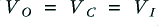 . The important feature of the operational amplifier (shown as a triangle in Figure 2) is that it does what it can to keep the voltages on its two input identical. So this result is how it achieves this goal when the input is steady.
Now consider what happens when we start to change the input so that after a very short time,  , it has changed by an amount
  to a value
  . The amplifier senses this change in input voltage and now has to force the other input it sees,
  , to change by the same amount. But to change the voltage on a capacitor we have to add or remove some of the charge it contains. i.e. we have to provide a current for the capacitor,
 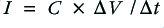 . It provides this current by altering the output voltage and producing a potential difference across the resistor,
  . This means the output voltage has to have a new value
For a series of input samples we can change this into another form
where the  values are the previous (old) and new inputs, and the
  value is the new output.
However the result is that the capacitor voltage now changes to the new output value. So after having worked out the above we now need to say that
before doing the next calculation for what will happen when the next sample arrives. We can then loop around doing this pair of calculations to keep updating the state of the system as we run though the series of input values. This generates a filtered series of values,  , from the input series,
  . As described the process relies on the unspoken assumption that
  . If the time constant value is small we would have to use a more complicated argument.
The above approach is what can be called a ‘timestep’ description of the analogue filter which is then used to write some equations to be able to carry out a sample-by-sample calculation that mimics the filtering action when we have sampled data. In the case of !TrackLPvax the filtering is much more complicated. This is partly because the RIAA filter involves more than one time constant. Also partly because I wanted to generate acceleration values, which are related to the rate of change of the velocity of the stylus. But the basic argument used is as outlined above. In principle you can replicate any analogue filter arrangement using this general approach. So if you are familiar with analogue filters and AC circuit analysis you can use that as a basis for building a computation to similar filtering upon sampled sound data.
Jim Lesurf
1400 Words
12th Oct 2007