Arm resonances and Turntable acoustic feedback
During the period of the late 1970’s and early 1980’s, a series of reviews were published in “Hi Fi News” that carried out some tests which sought to quantify the level of resonances and acoustic feedback in turntable/arm/cartridge combinations used to play Vinyl LPs.
These tests fell into two general categories:
- High-resolution frequency response tests intended to identify arm resonances
- Measurements of the output produced by exposing the system to vibration
Measurements were also made of other factors such as the LF resonance of arm/cartridge combinations. When considering the following, bear in mind that the test results described here are on equipment of around 20 years ago. Hence more modern equipment may well be significantly better in many cases! The results did, however, show the kinds of problems that arm/turntable manufacturers must tackle. Also, since measurements of this type now seem to be performed rarely, it may be that some currently available LP playing systems do exhibit problems which are not identified by the usual reviews in magazines.
Let’s first consider arm resonances excited by vibrations from the stylus.
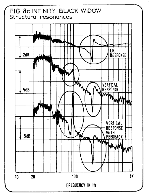
Various turntable/arm/cartridge combinations were tested. The earliest example I have so far found was in the March 1978 issue. This examined six pickup arms including the SME II (improved) and SME III. In order to explain and illustrate the nature of these measurements I will, however, use the example of the “Infinity Black Widow” arm which was reviewed in the May 1980 issue. It should be emphasised that I have chosen this arm purely for the purpose of a clear example. Other arms may show similar effects.
Measurements of the frequency response of an acoustic transducer like a cartridge/arm or a loudspeaker tend usually to be done with a modest frequency resolution which has the effect of smoothing out any very narrow resonances. However NK adopted the policy of carrying out measurements with a relatively high frequency resolution, precisely to show up any narrow resonances.
Figure 1, above shows the result of such a measurement upon the Black Widow arm, using a Stanton cartridge. The upper trace shows the left-hand channel response. The middle trace shows the vertical (antiphase stereo) and the lower the vertical when the output of the system is amplified and played in the room where the arm is situated at a level NK regarded as appropriate. Looking at the plots we can see distinct resonances at around 100Hz and 200Hz. These are most acute in the vertical plane of vibration, and are visibly enhanced by the presence of coherent feedback. These resonances are large enough that it seems reasonable to suspect that they would be audible.
Other arms showed resonance patterns which differ in detail from the example used here, and some arms had a lower level of resonances. However, in general, resonances of this type were exhibited by most arms. It is worth bearing in mind that the degree to which such resonances will be excited will depend upon the compliance of the stylus being using. A high-compliance stylus assembly (as tends to occur with MM designs) tends to impart much lower levels of vibrational force to the arm than does a low-compliance (often MC) stylus. Hence the size of the resonances will be smaller with high-compliance stylus cartridges. For this reason the resonances may matter less when using some cartridges than others.
Later measurements tended to show that examining the crosstalk was a sensitive way to detect resonances. In principle, there should be no output at all on the ‘quiet’ channel, but any resonance tends to be preferentially in a plane not aligned with the +/-45 degree axes of the LH or RH signals. Hence unwanted resonances tend to show up more clearly in such crosstalk measurements. It may be that this affects the clarity of stereo imaging. However it is unclear to what extent this may be significant in terms of having an audible effect for any specific arm/catridge combination.
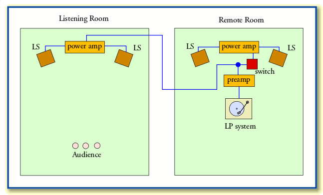
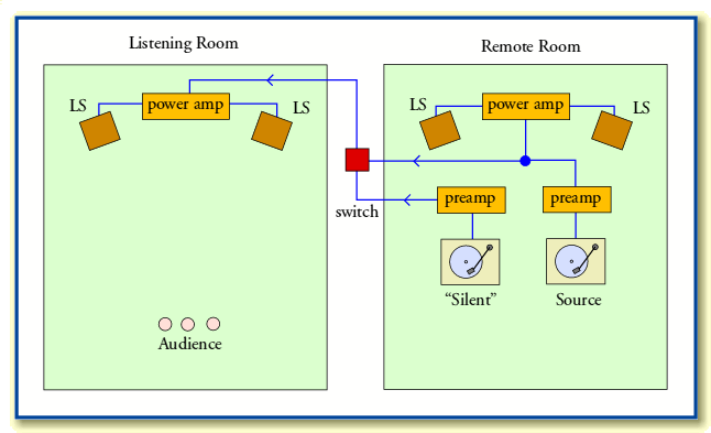
Now let’s consider the question of sensitivity to acoustic feedback in more detail. This can already be seen to be an issue from the Black Widow example shown above. To tackle this NK employed a “two rooms” method which can be understood by considering the following diagrams.
The rooms were far enough apart so that listeners in one could not directly hear the sounds from the other. Signals could, however, be sent from one room to the other via cabling. This arrangement was used in two ways.
In the first test arrangement, illustrated above, a complete LP replay system was assembled in the “remote” room, but a copy of the signal it produced was also fed to amplifiers and speakers in the “listening” room. A switch could be used to turn on and off the signal to the loudspeakers in the remote room. This means the listeners could hear the LP system playing whilst – depending upon the setting of the switch – the LP system would either be immersed in the sounds it was producing, or be in a quiet room. By operating the switch, the listeners could therefore test to see if subjecting the LP system to the sounds it was producing altered its behaviour in an audible manner.
The second arrangement, illustrated above, placed two LP systems in the remote room. One was used to play music in that room. The other was used to play a silent test disc, and the output from either system could be fed to the listening room. In both arrangements, the two sets of amplifiers, speakers, etc, were chosen so as to be similar, and adjusted to have similar gains. In this second system, a switch could allow the listeners to hear either the music being played by the source LP system, or any output produced from the (ideally) “silent” system. The signal levels induced into the silent system by being immersed in the sound vibrations of the source system could then be heard and measured relative to the output which caused them. This allowed the effects of any vibration sensitivity or feedback to be heard and measured.
A variety of LP systems were tested in the general manner outlined above. Some details of the tests were omitted from the resulting reviews, so it is not possible to comment on the level of calibration accuracy, etc. I may also have misunderstood the details as the descriptions given are not always clear on some points. In addition, we can expect the sensitivity of an LP system to vibration to depend upon the acoustics, its location in the room, the details of its supports, etc. Very little information about these details was given. Hence the results must be interpreted with caution. However, that said, the general results were quite interesting in showing that some LP systems had quite high levels of feedback sensitivity.
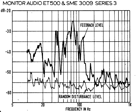
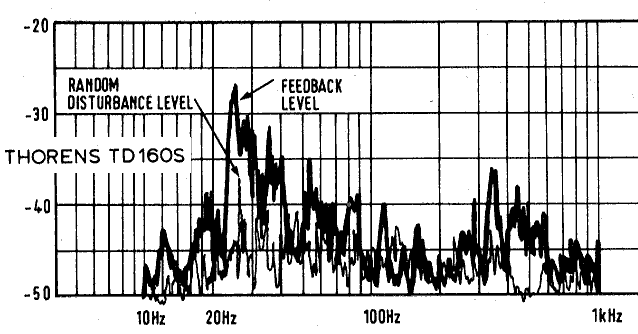
Here for the sake of illustration we can show example results of just two LP systems which were highly regarded at the time of their manufacture. These are the Thorens TD160S (Reviewed March 1981) and the Monitor Audio ET500 + SME Series 3009/III (reviewed October 1979)
The above image shows the resulting feedback-induced level when using the Monitor Audio and SME combination.
The above shows the results using the Thorens TD160S.
In each case, the signal level induced by acoustic feedback is apparently, at its greatest, between -25dB and -28dB below that of the signal level which provokes the feedback.
The above results are “open loop” so do not take into account any multiple-pass feedback. It should also be noted that the level observed will depend upon the gain settings of the amplifiers, and the acoustic couplings of the two systems being similar. Some of the arm+turntable combinations tested showed much higher levels of acoustic sensitivity, and produced feedback levels only -15dB below the initial signal. However it should be noted that turning up the volume control of the amplifier will tend to increase the feedback level, so when playing at higher gain the feedback may be much worse (higher) than indicated here. As a result, comparisons between tested LP systems may not always be fairly judged from the results obtained. At high volume levels acoustic feedback may be quite significant, and it seems reasonable to suspect it will have an audible effect in some cases.
It is also worth noting that in a normal system where the entire system is in one room, the acoustic signals being picked by air or support vibrations are a delayed version of what the LP system is producing. This means the feedback has a coherent relationship with the signal. This means the changes in the overall system response can be greater than we might expect. At frequencies where the delay (mainly the time taken for the sound to propagate from the speakers to the LP system) is an integer number of cycles, the signal will vector-add. At frequencies where the delay is an integer plus a half cycles, they will vector subtract. Taking -20dB as an example, this means a feedback level of 0·1 in amplitude. This would mean a change in power of a factor of between 1·12 or 0·92 – i.e. between +0·8dB and -0·9dB – depending upon the phase relationship between he direct and fedback signals. Such changes in frequency response are large enough for it to be a reasonable expectation that they will be audible. It should also be noted that open loop measurements will tend to slightly under-estimate the effect when the loop is closed due to mutiple-pass feedback. Hence we would require the level of open-loop acoustic sensitivity to well below -20dB in order to ensure that the system is not audibly effected by feedback.
In practice, the level of feedback will be affected by various factors:
- Gain level of the amplifiers and sensitivity of speakers.
- Location of LP system and loudspeakers in the listening room
- Mounting arrangements of LP system and speakers
Factors like the above may explain why different people tend to report varied performance and reactions to a given LP reply system. For example: If you tend to play music at high volume, then the loop gain may be higher, and feedback may then change the sound more than when someone plays a similar system at lower volume. As a result, the significance of problems like these may vary from one user to another.
All the graphs shown on this page are copyright Noel Keywood and Hi Fi News magazine. Text copyright J. C. G. Lesurf
