Materials and Devices for RFI protection
On a previous webpage I have already investigated using conventional passive components like capacitors and inductors to reject RF interference from mains power wall sockets Here I want to examine the properties and use of some special materials and devices often employed in mains RFI filters.
Ferrite Devices
Many mains filters employ Ferrite materials. These have some useful properties and can be employed in various ways. To understand how they work we can start by looking one of the simplest and most easily used types of Ferrite filter for mains leads.
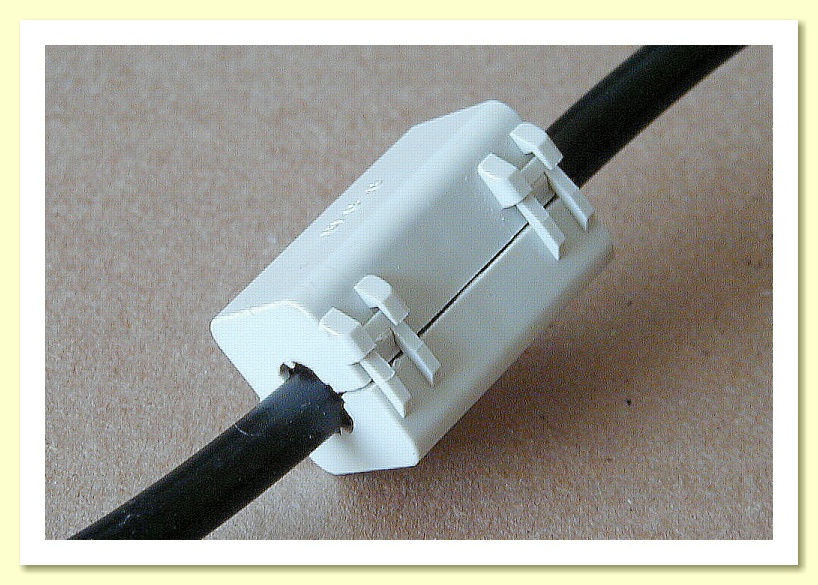
The photo above shows a typical device. It consists of a block of ferrite material that can be clamped around a mains cable and surround a section of the cable. This means it is exposed to the Electromagnetic (E and H) fields around the cable.
For the sake of clarity let’s assume the mains cable only has two wires – Live and Neutral. Electromagnetic power can propagate along the wires in two distinct ways or ‘modes’. These are called Differential Mode and Common Mode. Figure 1 illustrates these two modes of operation.
Figure 1 illustrates the two modes. On the left we can see a Common Mode RF voltage ‘spike’. Here the interference voltages on the two wires are identical, and they produce the same amount and direction of current on each wire. On the right we can see a Differential Mode ‘spike’. Here the voltages on the two wires are equal but of opposing signs, and the currents are in opposite directions.
Wiring actually conveys power by guiding an Electromagnetic Field along the path of the wires. Each of these modes will therefore carry its power in the EM fields around the wires. When we put a block of Ferrite material around the wires it will become immersed in these fields. Ferrites interact with magnetic fields and have two significant effects. One is to increase the amount of energy required to produce a magnetic field. The result is to increase the inductance of the system as we require more energy to get a given current to flow along the wires. The other is that the Ferrite can also dissipate some of this energy, so increasing the resistance experienced by the currents.
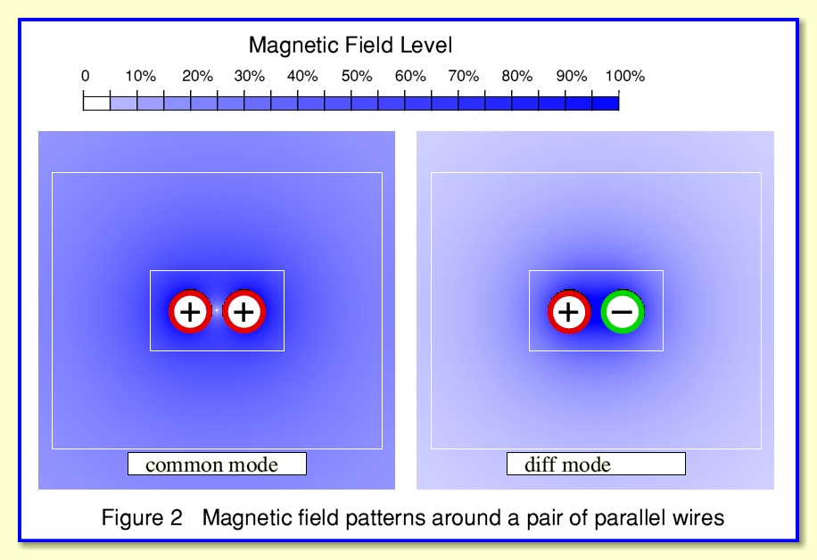
The distinction between Common and Differential Modes is important for a reason which can be seen in Figure 2. This displays how intense the magnetic fields will be near a pair of parallel wires carrying current. On the left we can see the pattern when the two wires each carry the same amount of current, and the two currents are in the same direction – i.e. a Common Mode current flow. On the right the pattern is for when the two currents have the same size, but are flowing in opposing directions – i.e. Differential Mode.
On each diagram I have sketched in a pair of white rectangles to represent the boundaries of a region where we might put a block of ferrite material surrounding both wires. Comparing the patterns you can see that the block would be exposed to more magnetic field from a Common Mode current than from a Difference Mode one. As a result, a block of ferrite fitted around the mains cable will increase the RF inductance and resistance much more for Common Mode than it does for Differential Mode. This distinction is useful. The 50Hz mains power is essentially Differential Mode since it supplies power by having different voltages on the Live and Neutral wires. And the mains power currents that result are equal and opposite in the Live and Neutral wires. As a result the ferrite block won’t present as high an inductance to the wanted mains power as it does to any Common Mode interference.
This behaviour allows the designer to minimise the effect of the filter on the wanted 50Hz mains power whilst getting a high series impedance to help reject Common Mode RF interference.
‘Clip on’ ferrite blocks are easy to buy and use. However they tend to work best at high frequencies unless you have a large chunk of ferrite extending along the cable. There are however some alternative arrangements which can give high Common Mode series impedance. These are based on using rings or loops of ferrite materials. In fact these filters are topologically similar to a clip on block as can been seen by looking at Figure 3.
The diagram at the left in Figure 3 represents a pair of wires (Live and Neutral) running though a tube or loop of ferrite material. The diagram in the middle shows a similar loop or tube, but this time the wires have each been threaded though the loop three times by adding two ‘turns’ to the path of each wire. Note that the way this has been done means that each time each wire passes though the hole in the loop it always goes though in the same direction. If we compare this with the diagram on the right we can see that the middle diagram is essentially a sort of transformer where each wire has two turns. The diagram on the right represents a transformer where each wire is passed though the ‘hole’ many times to make multiple turns. Hence in effect the transformer on the right is equivalent to re-using the same lump of ferrite many times as a Common Mode rejection device! The result is we then get a much bigger series inductance – for Common Mode – from a given amount of ferrite material.
Various practical RFI filters make use of ferrite cored transformers similar to the arrangement shown on the right in Figure 3. The Live and Neutral wires are wound a number of times around a loop of ferrite material, effectively multiplying the inductance and resistance it adds in series with the wiring for Common Mode interference. This means filters of this type can have much higher levels of RF rejection for Common Mode interference. But at the same time the required 50Hz mains power, being Differential Mode, is able to pass though the ferrite transformer device fairly easily. It doesn’t experience the same high series impedance as any Common Mode interference! Of course, that means that just using such a device won’t really reject Differential Mode interference, so such filters may then need to deal with that in some other way.
As with filters using conventional passive components, those using ferrite devices can take various forms. And complicated filters involving more components may offer improved performance if well designed. Figure 4 shows one possible circuit that could be employed. In this case I have omitted resistors in series with the capacitors, but they may well be included in a practical filter. The example makes two uses of ferrite materials. One is in a Common Mode ‘choke’ (actually a transformer of the type described above). This is followed by another stage that has two separate ferrite loaded inductors, employed to reject RF interference that isn’t Common Mode. Hence the overall design tends to reject RFI in general.
Loading a coil with ferrite increases its inductance. The ferrite will also add series resistance at RF. Unfortunately the effectiveness of ferrite materials tend to reduce if the magnetic fields applied are too large. So if the current though a ferrite-loaded inductor rises above a given value the inductance will fall and the ferrite ceases to work as intended. As a result, mains power current may reduce the effectiveness of ferrite in such inductors.
Large currents are less of a problem for CM chokes. This is because for 50 Hz mains power the currents in the Live and Neutral wires produce magnetic fields in the ferrite that tend to cancel out – as we saw in Figure 2. Hence we can run relatively large 50 Hz mains currents though a CM choke without the RF behaviour of the ferrite being degraded.
The VDR or Varistor
Another type of special device called the Varistor or VDR (Voltage Dependent Resistor) is often used in mains filters.
Most VDRs are made from a piece of Zinc Oxide or a similar material, usually doped with some other materials to adjust the electrical properties. The materials have the property that they exhibit a very high resistance when the applied electric fields are low. However they become considerably more conductive if the applied field is increased above a threshold value. A chunk of the material between a couple of electrical contacts will behave like a resistor, but with a resistance value that changes with the voltage between the leads. Typically the device will have a resistance well above a million Ohms for small voltages, but the resistance will fall to a few Ohms or less when we try to apply high voltages between the leads.
The device therefore shows a highly nonlinear relationship between voltage and current, as indicated by the Current/Voltage curve in Figure 5. Provided the applied voltage is well below a specific voltage, VN, the device behaves like a very high resistance and draws almost no current. But as the voltage passes VN the current begins to increase very rapidly if we try to make any further increase in voltage. In effect, the device behaves like a bidirectional Zener Diode. The manufacturer can alter the details of how the Varistor is made to adjust what value of VN the devices produced will have. So it is possible to make devices with various Varistor voltage values, VN. The devices can then be used to help control mains voltage ‘spikes’. Note, though, that mains ‘filters’ that only use VDRs are not necessarily filters in the sense that they pass some frequencies (e.g. 50Hz) whilst blocking others (RF). They filter on the basis of the sizes of the voltages presented to them, not the frequencies.
Mains ‘spikes’ or transients tend to be generated by switches like the thermostat controls that turn on and off inductive loads like fridge motors. These switching transients usually only last for a fraction of a second, but may generate large voltage spikes. Large voltage transients are in practice most likely to be a problem for equipment like home computers as the spikes could disrupt the digital electronics. But they can also cause bangs and rasping noises when listening to audio equipment.
Figure 6 illustrates a simple mains spike suppressor using 3 VDRs. The VN value for the VDRs should be chosen to be above the peak voltage for the normal clean mains sinewave. In the UK the nominal mains voltage is officially 230 Volts RMS +/- 10%. For a sinewave the peak voltages are 41% higher than the RMS value. So if we take the extreme case of mains power being 10% above 230V the mains sinewave will be peaking at 356 Volts. Hence the Live-Neutral and Live-Earth VDRs would nominally have to be chosen to have VN values comfortably above 356 Volts to avoid the VDRs needlessly drawing current at the peaks of clean mains. The VDR chosen to go between Neutral and Earth might have a lower VN because the Neutral line should not normally have such high voltages with respect to Earth.
The advantage of VDR suppressors is that they have no effect on clean mains, So they can’t disturb mains power reaching equipment when there are no spikes. Since they aren’t frequency sensitive they also can help block transients at low audio frequencies which might pass right though an RFI filter. In addition, VDRs respond very quickly to changes in voltage, so can react to transients that only last for a fraction of a microsecond. The snag is that simple VDR arrangements aren’t always effective at dealing with spikes as we can see from the graph on the right in Figure 6. This shows a section of 50Hz mains where two transient spikes in voltage have arrived. One (spike ‘A’) occurs near the peak of a 50Hz cycle and tries to produce a level that exceeds the VDR voltage. The VDRs essentially clip the peak off this transient and so reduce the size of the spike that would reach equipment though the VDR suppressor. The other transient (spike ‘B’) occurs at a different point in the 50 Hz cycle. This spike is as big as ‘A’ but the VDRs don’t react because the combination of the mains and spike voltages failed to reach the VDR voltage. Hence spike ‘B’ would pass though the simple VDR suppressor.
What type of filter to use?
Having examined how various types of mains RFI ‘filters’ work the vital question in practice becomes, “Which type and design is ‘best’ in practice?” Unfortunately, answering this question is difficult as the right choice depends on the details of the situation.
As discussed on another page, the behaviour of the wall socket will vary from place to place. And in some houses the problem is clicks and bangs from low frequency spikes, while in other houses some form of high frequency RF may be the source of problems. Hence the rather unsatisfactory general answer is, “It depends!”...
That said there are some general comments worth making.
Firstly “if it ain’t broke, don’t fix it!” i.e. unless you can definitely hear a problem like audible clicks and rasping noises, or local taxicab radios, don’t assume that your audio gear will sound better if you use some kind of mains filter.
Secondly, if the problem is occasional clicks or bangs from something like a fridge or central heating, then a cheap ‘spike protection’ or ‘surge protection’ filter or mains distribution board (i.e. one using VDRs) may help.
Thirdly, for RF interference a ’ferrite block’ on the mains lead (and perhaps around the loudspeaker cable) may help. Although note that you need to ensure that the block does have both the conductors that ‘send’ and ‘return’ the current though it to avoid also affecting the wanted mains (or loudspeaker signal).
You can obtain various types of basic filter from electronics companies like CPC, Maplin, RS, etc. Their prices tend to be much lower than from audiophile specialists. So you may find they can provide you with a relatively cheap solution to any problem. Worth considering them before considering more expensive alternatives. They sell various types of filter, clip-on ferrite blocks, filtered distribution boards, etc, that you can just connect and use. They also sell components designed for constructing mains filters. So if you have experience with practical electronics then is is possible to design and build your own mains filter systems. However there are obvious safety considerations and you would need to experiment, so I’d advise against doing that unless you know what you are doing and can proceed safely. This isn’t just a matter of avoiding blowing up your precious audio gear. You need to stay alive to be able to hear the music!
Jim Lesurf
22nd Mar 2010