Despite the arrival of the internet and streaming, podcasts, etc., many UK Hi-Fi enthusiasts still wish to go on enjoying ‘free to air” sound radio broadcasts. Alas, getting the best possible audio quality from these broadcasts tends to be a mysterious art – particularly when it comes to choosing and using a satisfactory antenna. The aim of this webpage is to provide some insight into this process and enable good results...
The UK has an extensive arrangement of VHF sound radio broadcasting stations. These tend to come in two types – the olde analogue ‘VHF’ broadcasts, and the newer digital ‘DAB’ broadcasts. There are a number of significant differences between these broadcasting methods which then require different forms of ‘demodulation’ to recover the stereo audio. But both types need a suitable receiving antenna to feed your chosen radio tuner.
In principle, a digital audio broadcasting system would be capable of delivering very high sound quality. Alas in the UK DAB has fallen prey to a “never mind the quality, feel the width” mentality. This means that the DAB broadcasts have been crammed with many stations at the expense of sound quality. Hence in practice, the older VHF system may be preferred by Hi-Fi enthusiasts. The old choice – quality versus quantity. Which leads us to the main aim of this webpage: To help those who want good sound quality to decide how best to achieve that aim! In practice, though, DAB may be OK for speech stations, but BBC Analogue VHF can offer better sound quality for music if you can get good reception and have an excellent tuner.
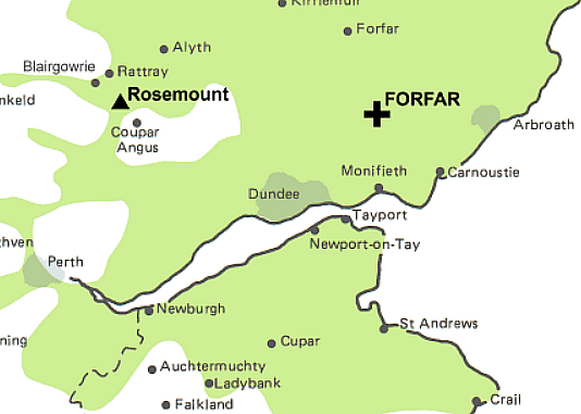
The map above shows the region around my main local BBC transmitter which is located at Forfar. Our house is about 25km to the south of that transmitter. We are fortunate that our house is up a low hill with a fairly clear line of sight to Forfar. I use an assortment of VHF antennas around the house. In in any room where I want to use a VHF tuner I set up an antenna for it. i.e. I don’t try to ‘distribute’ a signal from one main antenna to feed a number of tuners around the house. This eliminates the need for some kind of “VHF distribution amp” to provide enough signal for many tuners.
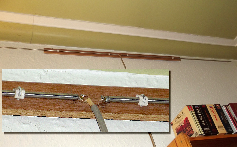
The above photos show the oldest installed VHF/FM antenna that I use. It is a simple horizontal 100MHz-sized half-wave dipole. i.e. the end-to-end length of the metal rod is half a wavelength for a 100 MHz radio signal in free space. There is a small break at the middle of the rod which acts as the ‘feed point’ that connects the cable that then conveys the received VHF signal down to the receiver. The inset photo shows it’s central part in more detail. Fairly obviously it is a ‘DIY’ antenna I made for myself from some metal rod and a wooden stick.
To show what this DIY antenna can supply to the tuner I used a computer ‘USB dongle’ and some DIY software which lets me use it as spectrum analyser. The results then let me plot the following spectrum of VHF signal power versus frequency.
This antenna is located near the NE corner of the house. i.e. as close as possible to the transmitter for an indoor location. Although in a room, not in the loft, it is up near the ceiling just below the loft. The length of the dipole is ‘tuned’ to work best for radio frequencies around 100MHz. So it is no surprise to find that it picks up the VHF/FM stations fairly well. But it does also pick up the DAB signals at higher frequencies. Note that – as with later spectra I’ll use as illustrations – the levels are all relative. I’ve not accurately calibrated the graph(s) because my interest here is regarding relatively how well different antennas works in differing circumstances. However the calibration would be that the “0dB relative” level corresponds to around 150 microVolts. ( i.e. -10dBFS then represents around 50 microVolts.) As a result the VHF/FM signals it produces are fairly strong and can give excellent results.
Note also that the ‘raw’ noise floor shown is due to the particular USB ‘dongle’ settings I used to obtain the spectral sweeps and my choice of resolution bandwidth, etc. What is shown is NOT the noise floor you’d get at the output of the tuner when listening to stereo broadcasts! Both FM and DAB use modulation systems that can deliver a higher audio output signal/noise ratio than the raw input signal/noise levels shown in such spectral sweeps!
The above scan was done in the same way as the first. However in this case the signal came from a horizontal 100MHz dipole in the loft. You might expect this to give better results given that it is higher. But in fact, overall, its Analogue VHF band response is poorer than that of previous antenna! Although higher it is located near the South end of the loft. i.e. at the ‘far side’ of the house so far as the arriving radio waves are concerned.
As a consequence it loses out due to the materials along, or near, its line of sight though the loft from the transmitter. Possibly also due to reflected signals from the various objects, surfaces, water pipes, etc. scattered around it. Despite the differences both antennas give audibly good results from Analogue FM VHF stations when used with various receivers ranging from an old Armstrong 626 to a classic ‘supertuner’, the Yamaha CT-7000.
The above antenna differs from the previous examples because it is designed mainly for use with a DAB+VHF/FM tuner. One annoying ‘feature’ of this cheap tuner is that it only has one RF signal input. Ideally, such a tuner would offer two inputs – one for the VHF band, the other for the DAB band. The reason being that for best results you’d need two distinct antennas which were sized according to the different radio wavelengths!
Given that I have some good FM tuners, I obtained the DAB+VHF one mainly for listening to ‘speech’ stations that are on DAB, but not VHF/FM. Hence the antenna used for this tuner is a vertical half-wave dipole whose length is approximately a half-wavelength for UK DAB broadcasts. For these non-Hi-Fi purposes it works fine. As with the other examples it is ‘home made’. In this case simply by tapeing two lengths of wire to a wooden stick sold for supporting garden plants, and connecting them to a coaxial cable! The result works OK for speech via both DAB and VHF/FM - despite looking crazy and being tucked away in the SE corner of a room!
Given the nature of this antenna the results aren’t a surprise. Overall it picks up a larger signal for DAB than the 100MHz dipoles. However this antenna also picks up the VHF/FM transmissions surprisingly well.
One omission from all three of the above ‘DIY’ antennas is that I didn’t bother to include a item called a ‘balun’ in any of them. Well-designed antennas tend to include this device. The reason being that the incoming EM wave induced equal but opposite voltages between the two locations on either side of the central gap. However the UK tends to use coaxial cable to convey the received signal down to the receiver. This presumes that the outer part of the cable is at ground potential and does not vary. The result of omitting a balun is that the cable tends to become a part of the antenna! Which can alter the signal level reaching the tuner, increase sensitivity to interference, etc. That said, having the cable become an active part of the antenna can also sometimes give a bigger signal! So omitting a balun can sometimes be helpful rather than a problem. As with many other aspects of choosing and installing an antenna it depends on the details of each specific case. Although having a balun is generally good as it helps avoid problems.
The above results show quite clearly that a big factor here is: “Location, Location, Location!” i.e. it is often worth experimenting with a simple half-wave dipole in various places around your house. You may well find that a particular place in a room can deliver a stronger signal that allows your chosen tuner to work well. It isn’t inevitable that you need an expensive and complex antenna system in your loft, or up on a mast above your roof. Note I live 25km from the transmitter, so distance also isn’t always a problem.
The common assumption for UK Hi-Fi enthusiasts is that a VHF/FM antenna should have its dipole and any other added ‘elements’ aligned horizontally, whereas UK DAB antennas tend to be vertical. The original UK VHF/FM broadcasts mostly used horizontal (E-field) polarisation and this seems to have “stuck in the folk memory” of UK Audio enthusiasts. However the reality now is that most VHF/FM broadcasts these days use ‘mixed’ polarization, not plain horizontal.
This change happened for two reasons;
As a result the BBC and commercial broadcasters changed to broadcasting ‘mixed’ polarisation some decades ago.
So far as Hi-Fi enthusiasts are concerned most portable radios would be regarded as not up to producing high fidelity. Indeed, many portables are only monophonic and use a loudspeaker and case that also cripples sound quality! Hence listeners who want the best possible sound will tend to choose a ‘good’ radio tuner and an antenna that can supply that with a suitable input signal. However the key question then is, what antenna arrangement to choose? In particular, how to get excellent results while avoid choosing an antenna that is needlessly complex, large. expensive – or even not work as well as a simpler and cheaper alternative which you can fit somewhere in your home!?
There is an understandable urge on the part of Hi-Fi enthusiasts in the UK to go for the “biggest and best” antenna they can find for VHF/FM reception. In contrast DAB gets little attention because the ultra-low bitrates and encoding it uses tends to degrade sound quality when it comes to music. VHF/FM tuners also vary considerable in their behaviour. Some need a stronger input signal than others. However a tuner can be overdriven when the input level is too high for their electronics, and their performance then becomes audibly degraded! As a result, what might be ‘best’ leads to answers that may start with: “well, it all depends...” Which means looking at some of the main aspects that affect choosing the ‘best’. Along with trying some experiments if you can.
The basic test/experiment is to see what results you can get from a fairly simple choice of antenna design and its location in your home, using your preferred tuner. The measured examples I’ve already given above illustrate that, for example, simply putting an antenna in the loft doesn’t automatically ensure it will deliver better results than one that is well-placed in your listening room. However given a loft or use of an external antenna up above your roof you can also decide to have an antenna that is more than a simple dipole...
Standard VHF antenna designs
The BBC used to issue free leaflets, etc., detailing examples of basic VHF/FM antennas. These remain sensible designs if you decide you want to try to obtain a stronger signal to feed into your tuner. So, below, I’ve included diagrams illustrating the BBC-suggested designs.
The full design has four ‘antenna elements’ labelled ‘A-D’. Their lengths and spacing are ‘tuned’ to be optimal for the UK analogue VHF broadcasting band which uses radio (carrier) frequencies around 100 MHz. Note that I’ve followed the old UK units as used by the BBC and the dimensions are in feet and inches!
These elements should be metal rods or thin tubes. ‘B’ (shown in green) is what antenna engineers would regard as the ‘driven element’ and hence is necessary. This driven element is normally about a half-wavelength long. It has a small gap at its centre where you connect the cable that then feeds the signal it collects down to your VHF tuner. The added elements between the driven element and the transmitter are called ‘directors’ (shown in blue) because they ‘direct’ some added signal towards the driven element. The element on the other side of the driven element is called a ‘reflector’ (shown in red) because it reflects some signal power back onto the driven element. The supporting ‘boom’ can be metal, although a boom of rigid plastic, or wood (i.e. a non-conducting material) might be better.
The trade-off in the choice of elements is that the more elements you include, the higher the ‘gain’ will be. i.e. you can hope to pick up a stronger signal. The basic antenna is just one element – B, the driven element. Adding A and C will given a higher output, and adding D to this will slightly increase this gain. Although it is a point that most explanations omit, note that adding elements may also make the antenna more sensitive to other objects nearby around it. Thus in a loft or near your roof the simpler antenna arrangements might work better than those with more elements in some cases! So if you want the best results it remains wise to experiment and discover what, where, given preferred results.
Another factor here is that the signal levels you can receive vary with time. In particular with the time of day and the weather. So any experiments or tests on a single day may not alert you to what will happen the next week, or even later the same day – let alone six months later when the typical atmospheric conditions may be very different. This also depends on you location, and how well your chosen tuner can cope! Note also that if you use more than two elements it can help performance if you use a ‘folded dipole’ as the driven element. As per the diagram below:
Understandably, the temptation is to go for the ‘full monty’ and buy/build/use the full 4-element type. However it is possible for too strong a signal to overload the tuner and degrade audio performance. A risk enhanced by the presence in many places of other VHF signals which may get fed down to your tuner. So be cautious of assuming ‘the bigger, the better’.
As mentioned earlier, antenna installation often takes for granted that the elements should be aligned horizontally. But it is possible in some cases that having then vertical might give better results. As with finding the best place in or above your home, this is best determined by experiment.
Also, bear in mind that professional antenna installers (or retailers!) may be keen to (ahem!) optimise their profits and minimise their costs/time! This preference can show up in two ways. One is to sell you a huge expensive antenna that has far more than three or four elements on a “bigger must be better” basis. This may then need to be located up on quite a tall mast which might well mean a simpler antenna that high would have worked just fine at lower cost and less risk of windloading (or bird-loading!) problems later on! There will be cases where a large, complex antenna may be needed – but most people really shouldn’t need one. And a risk can arise of overloading the tuner, degrading its output sound quality!
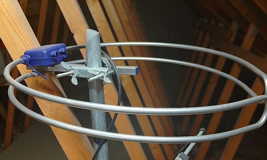
My thanks to Karl Kozurek for kind permission to use his photo of a halo antenna
At the other end of the scale, you may find the antenna installer suggests a ‘halo’ (circular) antenna. These are generally in the form of a folded dipole that has been warped round into a Horizontal loop. These save the installer time and effort because the installer doesn’t need to know precisely which direction the broadcast is coming from. They will collect signal power with much the same efficiency from any direction around the horizontal plane! So a quicker, “install and present the bill”, job for the fitter! The snag is modest gain, and slightly greater exposure to interference from houses, etc., around you.
Of course, you may live in a place where you wish to listen to strong VHF broadcasts coming from more than one direction. If so, the halo may be what you need. And, as my practical results showed, a simple dipole (and hence a halo) may work fine when positioned sensibly. But bear in mind that a simple vertical dipole would also tend to let you pick up signals from all horizontal directions, and is cheaper and simpler to DIY than a halo.
The ultimate factors here, of course, are you choice of tuner and the details of the broadcasts you wish to listen to. These are, for various reasons, also factors when choosing a VHF antenna. For example, if your preferred tuner isn’t very sensitive you might need a complex antenna (or use a VHF preamp) to give it a signal strong enough to allow it to work well. Other tuner designs might be more sensitive, so require less signal power to work well – but may be ‘over driven’ by a very strong VHF input, causing the output sound quality to be degraded! ...and of course, some tuners might be insensitive and overdriven by even a modestly strong input! In some cases affected by input at VHF frequencies that are quite different to the station you wish to hear!!
A snag here is that the information on specific tuners – both in maker’s literature and in many old reviews – often doesn’t cover that issue, or requires knowledge on the part of the reader to recognise hidden snags. So having looked into antennas, the next step should be to assess the ways in which your tuner affects what might be the best antenna arrangement for you to choose to enjoy the stations you want to hear... Stay tuned for that. :-)
Jim Lesurf
3000 Words
8th Sep 2024