Note: As I live in the UK, the details given here are based on the UK standards for VHF/FM Audio broadcasting. Some details may differ in other countries.
On a previous webpage ( https://www.audiomisc.co.uk/VHFAntennas/VHFAntennas.html ) I exampled the performance of simple DIY FM antennas for use receiving sound broadcasts in the UK. This page examines “what happens next” to help shed some light on choosing a good tuner to give the best audio fidelity for listening to stereo broadcasting when fed from such an antenna. As with the previous page, the measurements here were made using a “FUNCubeProPlus” (FCPP) USB computer ‘dongle’ which had been calibrated.
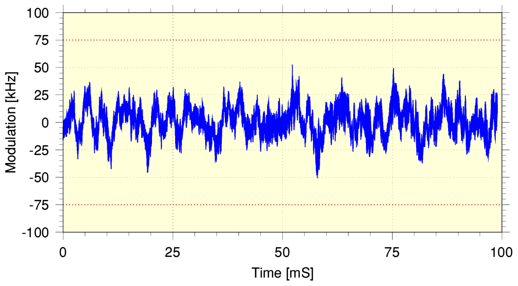
The UK system is based on frequency modulation which is strictly limited to +/- 75kHz from the nominal carrier (i.e. unmodulated) radio frequency. (In practice, for stereo audio the BBC tend to actually try to keep the level of modulation down to +/- 50kHz.) I did some quick initial signal captures and processed these to find results like that shown in the graph, below.
This graph covers a 100 millisecond portion captured from one of the BBC stations and shows the pattern of frequency versus time modulation that represents the audio waveforms It confirms that the peak modulation is kept below +/- 75kHz. The nominal allocated channels are 200 kHz wide, thus this should ensure that each broadcast station ‘keeps to its allocated bandwidth’.
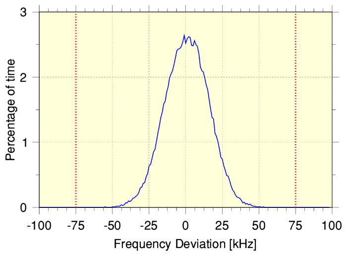
The graph above is a histogram which shows the relative percentage of time the broadcast’s modulation causes the frequency to reach various deviation levels. It is based on a longer duration of measurement and confirms that the signal keeps to its allocated channel. Hence we can expect that a tuner which can employ an ideal filtering system that passes the allocated 200 kHz band whilst rejecting signals at all other frequencies would ensure we select the wanted audio whilst blocking effects from RF in adjacent channels.
Knowing the above, the key question when you wish to listen to the conveyed audio becomes: what choice of tuner + antenna combination will give me the best sound quality? As is often the case in life, being able to answer this question involves an amount of “it depends...”! Having looked into antennas this page now turns the focus onto the choice of tuner.
What isn’t clear from the above FM radio signal measurements is some of the consequences which arise from the properties of Frequency Modulation. Effects that may be more prone to arise when we have to tune into a stereo FM broadcast! The FM broadcasting system was devised and came into use in a ‘mono era’ Its agreed radio channels, etc, were designed for good monophonic audio. Years later, stereo then had to be wedged into these channels, and compromises became unavoidable. Particularly when the number of radio stations increased, sometimes requiring them to broadcast shoulder-to-shoulder! This problem is an issue I examined and explained on a previous webpage you can find at https://www.audiomisc.co.uk/HFN/BandwidthBlues/page.html
There is a general opinion amongst Hi-Fi enthusiasts that the modern ‘digital’ tuners give poorer sound quality than the best, older, ‘analogue’ designs. That may or may not be so for any given model of tuner, but in principle, either approach should be capable of much the same performance. So this depends on the details of the design and manufacture in each case. I can’t help wondering if a digital tuner could be made to work superbly well – if someone applied the required skill and determination.
However at this point I’ll concentrate on analogue tuners because these are most often preferred and used by UK Audio enthusiasts – and some superb examples have been made and sold. For these the filtering effects outlined on the page I linked above tend to determine the limits to performance given an RF input of optimal amplitude.
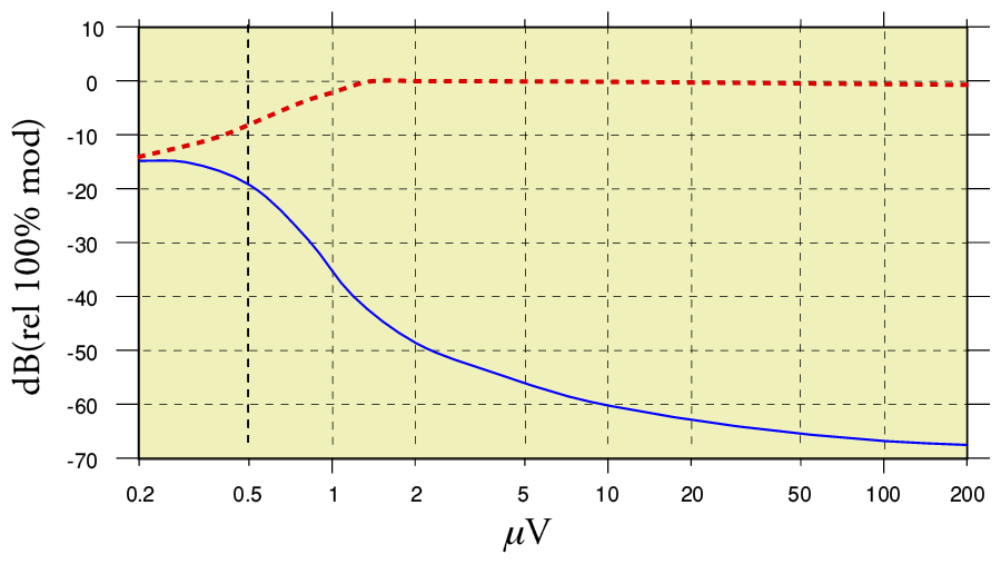
The graph above shows some results for the old ‘classic’ Armstrong 600 Series FM tuner, as measured in a Hi-Fi News review of the period. This gives us the basic information we need to decide if that choice of tuner would suit our antenna. The FM system has the property known as ‘noise quieting’ – i.e. as the received FM signal level rises the level of background noise we hear when listening to the audio output tends to fall. The blue line on the graph shows how the output audio’s noise level varies with the input signal level. This shows that in the case of the 600 Series tuner a VHF input level of just 2 microVolts (rms 75 Ohm input) would provide a background noise level that is around 50dB below the sound level of a +/-75kHz modulated audio tone. An input of 20 micro Volts reduces this background level to below 60dB. This is generally suitable for most normal listening. Indeed the BBC’s FM broadcasting arrangements aim to provide at the transmitter a ‘noise floor’ around -65dB.
The broken red line shows how the output audio level varies with the input VHF level. When the input level is very low – less than a couple of microVolts – the signal becomes too small and it can’t fully ‘drive’ the FM demodulator in the tuner, hence the audio output is reduced. Above about 2 microVolts the output audio level ‘saturates’ or ‘limits’. As a result, with an input of 2 microVolts or more the tuner is said to be “into limiting”. This is useful as it is taken to assume that once the tuner is ‘limiting’ it will tend to reject or suppress any fluctuations in the amplitude of the input VHF signal being received from affecting the audio output.
On that basis we could conclude that the simple dipoles whose output I measured and discussed on the previous webpage can be expected to give satisfactory results. This is likely to be the case – but there are some potential snags which depend on your local circumstances. A point worth making here is that ‘bench test measurements’ on a tuner tend to simply connect a cable from a VHF/FM signal generator to the tuner’s input. That shields the tuner from various aspects of reality when used with an antenna to listen to FM radio! The most common ones being:
Ignition Interference has tended to come from poorly maintained petrol-fueled cars whose spark plugs need changing! ‘Sky Noise’ is a general term for background noise from the environment and it may come from a range of sources - some genuinely astronomical - but also from man-made causes of background radio noise.
Weather events stem from natural processes that create variations from place to place in the atmosphere. In particular, variations in density, dampness, and temperature. These factors produce patterns of variations with location in the refractive index and transparency of the atmosphere. The result is that the VHF waves may be attenuated, or diverted – or even focussed! - onto your receiving antenna, causing the signal level to fluctuate. On occasion you may find the signal level falls to almost nothing. Whilst at other times you may find that distant VHF stations you can’t normally receive will become audible. Alas, sometimes then interfering with broadcasts from your ‘local’ transmitter!
In order to cover entire countries, terrestrial VHF broadcasting employs a number of transmitter locations, distributed to ensure most people will get satisfactory FM/VHF reception when using a decent tuner. The carrier frequencies are chosen so that adjacent transmitters use different ‘channel’ frequencies. Thus when you tune into your local transmitter you shouldn’t usually get a problem caused by also getting a signal from other transmitters. that are in areas next to your own. Alas, at times the weather can cause VHF broadcasts to reach further, and can then cause interference. This is largely a matter of a combination of the weather and where you happen to live. But it can cause severe forms of ‘multipath’ effects on occasion. Which leads me to...
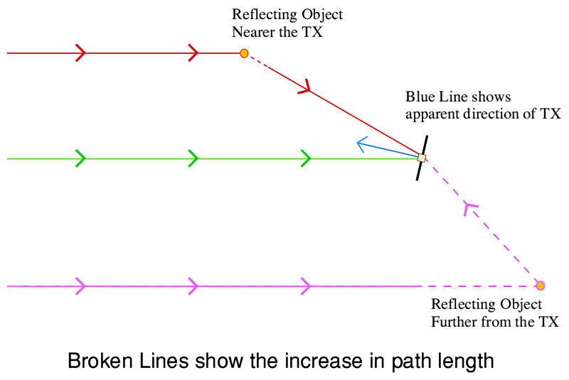
The above diagram illustrates the phenomenon usually meant by the term “multipath”. As the name indicates, it is a situation where objects can reflect or scatter some of the radio broadcast radiation from a transmitter and direct it onto the receiving antenna. The antenna may then collect these waves and combine them with the direct signal. In the diagram the green line represents the main – direct - signal. The red line shows an object closer to the transmitter reflecting onto the antenna. The purple line shows a similar reflection coming from another object that is further away from the transmitter than your receiver. When these contributions are combined they alter the behaviour of the antenna. The simplest effect is that we may find that the ‘apparent direction’ to the transmitter – i.e. the direction which gives the biggest output – is altered. At first glance it may seem this is ‘good news’ as more signal energy is being directed at the receiving antenna. However there is a serious snag... These reflected contributions go via extended paths, so arrive ‘late’.
The most obvious effect of this can be seen if we consider ‘nearby’ reflections. The wavelength used in the UK is approximately 3 metres. Hence a reflecting object that contributes a multipath signal that is just a meter or so away from the antenna may actually reach the antenna half a cycle ‘late’ and thus largely cancel out the ‘direct’ signal! Alternatively. if it arrives one or two cycles ‘late’ it may actually increase the received signal level! Hence the sensitivity of antennas to nearby objects which might reflect in this way! For close-by reflections this can be either a bonus or a loss, depending on the antenna, its placement, and its nearby surroundings.
Reflecting objects much further away will, fortunately, usually only reflect a relatively low signal level onto the antenna. But for multipath from longer distances yet another set of effects can arise due to the way FM functions. The effect of a reflection depends on the relative phases of the direct and ‘delayed’ contributions reaching the antenna. This in turn depends on how many wavelengths longer the reflected path may be. FM uses variations in the VHF carrier frequency to indicate the audio signal pattern, and that in turn will alter the relative phases of the direct paths. When combined at the antenna the most obvious result is to cause unwanted rapid, FM dependent, changes in the amplitude of the RF signal being sent to the receiver. This gets more severe when more than one source of reflection contributes to the multipath. And the impact on the output audio can be markedly worse when receiving stereo broadcasts! It can then cause a range of odd distortions, and what came to be called ‘birdies’ – a sound like birds twittering and tweeting – to be audible along with the intended audio!
In general, reviewers have tended to assume that these problems are largely dealt with by the ‘limiting’ behaviour of well-designed FM tuners. For example, if you look again at the measured results for the old Armstrong 600 tuner you can see that once the received signal level is well above about 2 microVolts any increase in the input level has no effect on the amplitude of the audio output. Thus it is taken as a good sign that the tuner is good at ‘rejecting multipath interference’. Although there is some truth in this, the reality is more complex, and multipath may still lead to the output audio becoming distorted – particularly for stereo broadcasts.
Suppressing multipath effects involves more than simply having a low value for the onset of amplitude limiting. (If you wish to know more about this, see the BBC ‘White Paper’ obtainable from:- https://www.bbc.com/rd/publications/whitepaper184 .)
If your location is exposed to multipath effects it is worth being aware that this may be a reason for what otherwise might seem an odd decision: You might get better results by using a more directional antenna even if a dipole gives you a signal level that takes your tuner well into limiting! This is because the directional antenna, pointed in the correct direction, can let you get more input from the main path, whilst reducing what is picked up from multipath signals from other directions! Hence an antenna with 3 or 4 elements, aimed at the known direction of the transmitter, and well clear of nearby objects, may give better results in some cases. Not because it gets more signal, but because it reduces local multipath signals. Some ‘supertuners’ of the past provided a way for the user to detect the presence of multipath. That could be very useful when choosing an antenna and adjusting it for the best results. But sadly, this is something most tuners omit.
When choosing an FM tuner one other point is worth being aware of. Most tuners use a ‘heterodyne’ process which converts the incoming RF at about 100MHz down to one at about 10MHz. (More specifically, to 10·7MHz which has become a common standard value for this Intermediate Frequency.) This enables the tuner to use a set of ‘fixed’ filters and amplifiers in an ‘IF section’. The output from these fixed-frequency filters can then demodulated regardless of the actual received broadcast radio frequency. This arrangement makes it easier to get consistently better results over a range of broadcast frequencies.
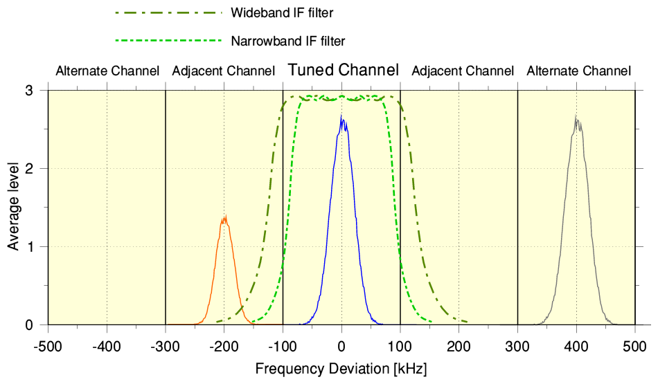
The IF filters are designed to pass the wanted station’s signal whilst rejecting any input at other frequencies. In the UK the situation can be represented by the above illustration. Each channel allocation is nominally 200kHz wide.
The zero frequency on the graph represents the IF frequency (actually 10·7MHz) of the station you are tuned to. So the blue line represents the station you tuned into and wish to hear. The red line represents a low signal level signal from a distant transmitter which is using a VHF frequency channel adjacent to the one you want. The grey line is another station from your area’s transmitter. This is two channels higher than the one you wish to hear - i.e. the upper ‘alternate’ channel. The IF filters are intended to pass the wanted station’s signals whilst blocking those from the other stations in the alternate/adjacent channels. However there is a practical problem here indicated by the broken green lines. These lines represent the frequency responses of two different IF filter designs.
Conventional analogue filters can’t produce a perfect ’rectangular window’ filter that passes a 200kHz band unchanged and totally rejects all else! Thus the designer of the tuner has to make a choice. They can provide a ‘narrowband’ IF filter as shown by the light green broken line. This does a good job of blocking any unwanted signals in the adjacent channels, but tends to also affect the wanted signal. Its passband isn’t very uniform and this alters the wanted signal. (Hence the ‘ripples’ in it’s less-than ‘flat top’ frequency response across the wanted IF range.) The result tends to be a slightly distorted audio signal, reducing the fidelity of the sound.
A wider IF filter (as exampled by the darker green line) will do ‘less harm’ to the wanted signal, and give lower distortion, etc. But it has a degraded ability to reject any unwanted signals in the adjacent channels. So may be more open to interference producing unwanted noises, etc as you listen! Most FM tuners choose some kind of compromise. After that it depends on how well that choice suits your local situation. However some of the better tuners offer a user-selectable choice and you can switch between narrow and wide filters to decide which you might prefer.
When considering which FM tuner to buy and use the bottom line here is that, yes, it is often a good sign when a tuner ‘limits’ at a relatively low input signal level. That does tend to indicate it will perform well when it comes to rejecting multipath effects But, in itself, it doesn’t guarantee the tuner will be immune. Similarly, seeing the tuner can offer a SNR better than 60dB when fed a low RF signal level is attractive because it indicates you should be able to get low background noise levels. However a bench test which obtains measured results like that is made by linking the tuner via a shielded cable to an RF signal generator. As a result it excludes any ‘sky noise’, man-made interference, or VHF signals at other frequencies, so the bench test results may not always represent what happens in your home when you connect it to an antenna that is exposed to ‘real world’ factors.
This all does raise a curious question:Why do ‘digital’ tuners have a reputation for being ‘bad’ compared with traditional ‘analogue’ tuner designs? Is this inherent, or prejudice, or simply that most (all?) domestic ‘digital’ VHF tuners sold in the UK tend to feature DAB/DAB+ which perhaps deserve the criticism they get in terms of poor sound!?
Digital designs using modern devices and Digital Signal Processing should to some extent be able to actually adapt to your local conditions by carrying out their own analysis and corrections to maximise their ability to recover the intended stereo audio and minimise – or in some cases remove! – the degrading effects. Yet so far as I am aware, no-one has done this.
So stay tuned, because I may look into that... :-)
Jim Lesurf
23rd Sep 2024