Digital Dividend, or Digital Distress?...


The UK has now completed the great ‘DSO’ or Digital Switch-Over – moving from ye olde Analogue TV to the brave new world of Digital TV. So you might think we could settle down to deciding if we’d be happy with Standard Definition pictures, or want an upgrade to High Definition. But if you think the upheavals are over, think again. The UK Government have been boasting for years about a ‘Digital Dividend’. But for millions of TV viewers it may come to look more like a looming Digital Disaster.

Another part of the bright vision of a high-tech future is ‘4G’ mobile. This is the 4th Generation of mobile devices, bringing higher data rates and greater power to mobile users. However current plans may mean that many of us will find it causes interference to our Digital Terrestrial TV (DTTV) reception. And by interference I don’t just mean occasional annoying imperfections to the picture and sound. It can mean a blank TV screen. To see why, let’s start by looking at the planned change that is just beginning to be rolled out across the UK.

Some of the details of what follows may be difficult to understand if you aren’t familiar with the relevant engineering. But if you watch Digital TV using a conventional UHF aerial, your viewing may well be affected by 4G. So the information may be important to you...

The Cunning Plan
The basis of the plan is that Digital TV allows us to cram TV stations into a smaller portion of the radio spectrum. Analogue TV needed an 8MHz wide channel to carry just one station. Digital combines a number of TV (and sound radio) stations into a ‘multiplex’ that can be fitted into the same bandwidth. So, the argument goes, fewer UHF channels should be needed even though we now have more stations to watch. Up until mid 2012 almost the entire range of radio frequencies from 470 MHz to 862 MHz has been devoted to TV. This UHF band was divided into a series of 8 MHz channels, numbered from ch21 at the low-frequency end up to ch69 at the high frequency end. Just three of these were reserved for non-TV special purposes. The great Digital Switch Over simply changed to using those existing channels for digital multiplexes, boosting the number of stations we could watch.

Fig01.png - 15Kb

Figure 1

However the mobile phone companies are hungry for ever more radio bandwidth. So the deck-chairs are to be moved again. In the period from October 2012 to October 2013 the channels will be re-allocated in many parts of the UK to ‘clear’ two parts of the spectrum.

Fig02.png - 14Kb

Figure 2

The relevant changes here are that what have been UHF TV channels 61 - 68 will be handed over to the 4G mobile service providers. Instead of TV, this part of the spectrum will be used for transmissions between 4G base stations and mobile devices. In principle, this is fine, but the devil is in the details.

Fig03.png - 24Kb

Figure 3

Figure 3 shows the kind of scheme planned for this part of the spectrum. It is worth noting that the final details of how the 4G system will operate was still under discussion when I wrote this, but something like the arrangements I will describe look like being the settled outcome after some years of argument... erm negotiation.

TV will continue to use the space up to and including radio channel 60. There is then a 1 MHz ‘gap’ which no-one should use. Above that are a set of channels the 4G providers will use. The 4G channels at the low frequency end – i.e. nearest TV channel 60 – are the ones that 4G base stations will use to send information to 4G mobile devices (i.e. downlinks). These will occupy the bandspace from 791 MHz upwards. The proposal is for six such 4G channels, each 5 MHz wide. As we go up further in frequency there is a ‘duplex gap’, then the set of channels that 4G will use to let mobile devices contact their base stations (uplinks).

The first aspect of this arrangement that will alarm experienced radio engineers is the 1 MHz ‘guard gap’. It means that the lowest frequency 4G base station transmissions will be very close, in frequency terms, to the highest TV channel transmission. 1 MHz at 790 MHz means only a tiny change of about 0·12% in frequency separates the two!

Probably the simplest way to illustrate the kind of interference problems that millions of viewers may encounter as a result of the 4G plan is to use a specific example – my own!

Fig04.png - 33Kb

Figure 4 Shown to the left

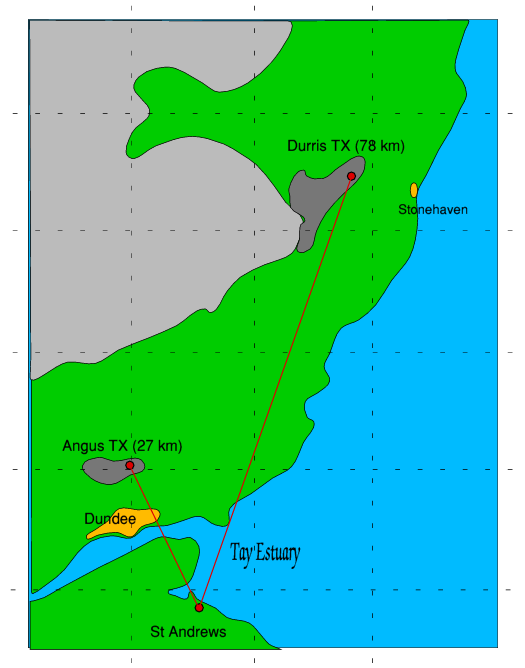
The map on the left shows where I live relative to the two closest DTTV transmitter sites. The nearest, Angus, is about 27 km away to the NNW. The best alternative I have to that is Durris, about 78 km away to the NNE. Durris is much further away, but the path is a relatively clear one.

Although there is no local 4G coverage as yet, the closest existing mobile base station to my house is about 400 metres away, also to the NNW. From where I live the direction to this site is almost the same as that for the Angus DTTV site. So when I and my neighbours point our TV aerials at the Angus transmitter we’re also pointing them at this base station!


If I connect an RF spectrum analyser to the coaxial cable that feeds TV signals to my living room I can measure the UHF signals I’m getting. Figure 5, below, shows the kind of results I get. The TV signals (multiplexes) from the distant Durris transmitter are shown at the low-frequency end. The signals from Angus are shown at the higher-frequency end, and can be seen to be noticeably stronger. This is because the Angus transmitter is much closer to where I live. Hence at present I get more reliable reception from Angus.

Fig05.png - 23Kb

Figure 5

The documents which have been published over the last year or two regarding the 4G proposal give varying details. This has been part of the process of debating what the final characteristics would be in practice. The base station power levels have been proposed in terms of a specified power spectral density for the allowed EIRP (Effective Isotropic Radiated Power) per 10 MHz of bandwidth. Documents suggest values from 59 dBm/10MHz up to 64 dBm/10MHz. For a 5 MHz 4G channel this corresponds to effective radiated powers in the range from just under 0·5 kW up to more than 1 kW.

Facts from figures.
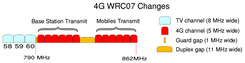
If you’re not familiar with units like ‘dB’ or terms like EIRP the following explanations may help.

‘dB’ (decibels) are regarded by engineers as a convenient way to indicate the relative levels of electrical signals like UHF transmissions. If one signal is shown as being 20 dB higher than another that means the power is 100 times bigger. 30 dB means the power is a 1000 times bigger. So a level of, say, -20dB is 30dB above one of -50dB – and is therefore 1000 times more powerful.

The voltages change more slowly because the power grows in proportion with the square of the signal voltage. So 20dB means the voltage is just 10 times bigger.

‘dBm’ has a slightly different meaning. There the ‘m’ stands for ‘milli-Watt’ (i.e. one thousandth of a Watt). Because of that, a value like ‘60dBm’ means ‘1000000 times more powerful than a milliwatt – i.e. 1000 Watts or 1 kW (kilowatt).

So a 4G base station transmitting an EIRP of around 60dBm/10MHz will behave like one radiating a 1000 Watts of Radio Frequency power in a 10 MHz ‘slot’ in the spectrum. In fact, the 4G power levels are rather higher than has in the past been allowed for earlier generations of mobile phone base station. The power needs to be high because 4G is planned to radiate much bigger amounts of information per second to provide all the fancy new 4G features! In engineering terms – higher data rates means higher transmitter power levels. Alas it can also mean stronger signals that cause more interference!...


For the sake of example I chose to assume that the value for a local 4G base station will be 0·5 kW for each 5 MHz 4G channel, and that such a base station is to be placed about 400 meters away from my location as described above. I then did a simple calculation, assuming I had a reasonable TV antenna (aerial), to estimate the relative levels it would feed down into my TV set.

Fig06.png - 20Kb

Figure 6

Figure 6 shows the results if such a 4G base station had already been turned on during 2012. Here I have shown the potential 4G signals in pink. Note that they cover the frequency band used for one existing TV multiplex (ch61), and are immediately adjacent to another (ch60).

Fig07.png - 19Kb

Figure 7

By the end of October 2013 the ‘4G clearance’ should be complete. At that point any DTTV broadcasts that were previously being transmitted above ch60 will have been shifted down to lower frequency channels. For Angus the result will then look like the spectrum shown above. Once this is done 4G will come into operation (now shown in red.)

The commercial multiplex that (in 2012) used ch61 will have been moved well down to ch49. However the main BBC multiplex (BBCA) will only be nudged down slightly to channel ‘60-’. Or at least, that is the current plan. The BBCA multiplex is important as it carries all the main BBC stations – BBC1, BBC2, etc. Under the current plan, the Angus transmissions will from 2013 onwards only be a few MHZ below the much more powerful 4G base station signals.

The TV multiplexes from Angus and Durris each give me signal levels on the antenna downlead somewhere between about 3 mV and 6 mV. Whereas a 4G base station placed at the local mobile phone site would produce about 78 mV for each 4G downlink channel. i.e. each 4G channels is about 20dB more powerful than the wanted DTTV multiplexes. Given six 4G downlink channels the actual combined voltage they will produce on average will be almost 200 mV! So the 4G signals will be much larger that the TV ones.

Anyone familiar with the design and behaviour of domestic TV sets, boxes, etc, will realise that this level of input is uncomfortably high. Loft distribution amplifiers that are used to distribute TV around the home may become overloaded. Similarly the front end of various TV sets, boxes, etc may overload. Or their automatic gain circuits may adjust to cope, but then be unable to detect the wanted – but much smaller - TV signals. Hence in such situations ‘interference’ would not mean a poor picture. It would be likely to mean completely losing the ability to receive DTTV!

The above situation is bad enough, but the reality may be worse. This is for two reasons.

Firstly, when estimating the level of the wanted TV signals for Figures 6 and 7 I assumed I could ignore losses caused by curvature of the Earth, scatter from buildings, hills, losses due to weather, etc. So in practice the TV signal levels I actually get (as shown in Figure 5) are much smaller than shown in Figures 6 and 7. This is particularly true for the more distant transmitter (Durris, shown in blue).

Secondly, the 4G channels may transmit rather more power than the 0·5 kW I’ve assumed for my example. That could push up the size of the 4G interference by about another 40-50 percent. i.e. to over 100 mV per 4G channel – around 270 mV in total. The outcome may therefore be that the 4G interference is rather more than 35dB bigger (i.e. about 4,000 times more powerful!) than the wanted TV signals. And I live almost half a kilometer from the location of the 4G site I’m assuming for my example. People who live closer will tend to be subjected to even higher levels of 4G interference!


The Effects of 4G interference
Broadly speaking we can divide the effects of 4G transmissions on DTTV into two categories.

For some homes where both the unwanted 4G and wanted DTTV are high enough it might be possible to ‘solve’ or reduce problems by attenuating the antenna output to produce an overall reduction in the levels. However since that would also reduce the wanted DTTV level you’d probably have to be lucky for this to work. More generally we need to look at a set of factors that will influence the outcome. The main ones worth looking at are

Mark Waddell of the BBC has put considerable effort into assessing the impact by making a number of detailed measurements on over a hundred examples of domestic DTTV reception equipment that he subjected to 4G-like interference. Here I will draw on his results to indicate what can be expected. I’d like to thank Mark for his kind permission to quote some of his results.

Fig08.png - 92Kb

Figure 8

The above illustration is taken from DTT Receiver Performance and LTE Compatibility by Mark Waddell. (LTE stands for ‘Long Term Evolution’ of mobile services, etc) The document is a set of presentation slides that show some of his results. For clarity only a few examples are plotted. The graphs show the minimum DTTV signal level required for a reference level of visible or audible errors in the DTTV output when a given amount of 4G ‘Interferer’ signal is present.

Since my previous graphs give levels in mV it may be useful to note that 10 mV corresponds to -28dBm, so 100 mV corresponds to -8dBm. To make the situation clearer, though, we can plot the behaviour of one example (called ‘RX1’ above) in terms of the voltages of the DTTV and 4G inputs.

Fig09.png - 28Kb

Figure 9

The blue line in Figure 9 shows the 4G level that could be tolerated when the base station was working at its 100% use level. (i.e. sending as much data as it can to as many users as it could handle.) The black line shows the 4G level that could be tolerated when the base station was ‘idle’. (i.e. when 4G users were being fed with data.) The broken red line indicates where the 4G voltage would be 50 times the DTTV signal voltage.

The most obvious point that jumps out when we examine the graph is that a change in the level of use of the base station can have a dramatic effect on how much it affects DTTV reception. This complicates the situation because we may find that DTTV reception in a home may come and go as the demand on the local 4G base station fluctuates. The result may be a householder who calls a repair engineer or tradesman because their set “doesn’t work”. Only to face the classic behaviour where the problem has evaporated by the time the tradesman arrives and checks the equipment! The result is a call-out charge, the tradesman leaves... and the problem comes back again once he has gone. This kind of unpredictable (by the householder) variation is characteristic of an interference source that employs some form of time-division pulsing or hopping that varies with its intensity of operation.

Different DTTV receivers are affected by alterations in 4G use levels in various ways. The impact will vary from one house to the next. In some homes, one TV in one room may work when another elsewhere in the house doesn’t. The outcome is one familiar for those trying to deal with interference effects in the real world outside the lab. It becomes a guessing game to determine the cause of the problem, with much wasted time and money, and considerable inconvenience and frustration along the way. It also opens the door to people being led into buying ‘solutions’ that may not work or are needlessly expensive. Possibly also a prime chance for door-knockers to go round milking the situation.

More generally it also means we have to decide which level(s) of 4G use we have to regard as ‘normal’ for the purpose of assessing impact. Should we always assume the worst case? Or some estimated ‘typical’ 4G pattern of use? And how to take into account variations in behaviour of existing domestic DTTV equipment? What about homes only affected during some parts of the year, or during specific weather events, when the DTTV signals fade or the 4G input rises? This becomes a minefield for those trying to estimate the likely impact in terms of annoyed householders who simply want to watch DTTV.

Let’s now focus on looking at the blue line in Figure 9 where the 4G base station is working 100%. i.e. the ‘best’ situation for the chosen DTTV receiver. As you might expect, the higher the received TV signal level, the bigger the amount of 4G interference which can be tolerated.

When the 4G interferer level is ‘low’ the TV set can work happily. For example, when exposed to a 4G level of around 20 to 25 mV the TV can work OK given just 0·5mV of TV signal. i.e. with a wanted TV signal voltage 50 times smaller than the 4G exposure. Alas, when the 4G level is higher the situation becomes far worse. When exposed to a 4G level of 100 mV the TV set needs 5 mV of TV signal to work OK. And in places where the 4G exposure is 200mV the TV needs 30 mV of TV signal to be able to work OK. Having increased the 4G voltage level by a factor of less than 10 we find we’d need to increase the wanted TV signal voltage by a factor of more than 60 to allow it to continue to work! In effect, the set becomes swamped if the 4G level is above about 100 mV. A situation that looks like being all too common for those living within half a kilometer of a 4G base station! This behaviour is a fairly classic response for a system being driven into nonlinear overload by excessive input signal levels.

The situation clearly becomes worse when the 4G usage changes down to being idle. In such circumstances the tolerance remains around 20dB (x10 in voltage) across a wide range of input levels. In this situation the 4G signals act as a very effective ‘pulsed jammer’ for DTTV reception!

Although it is hard to put an overall figure on this, it looks like anyone who is subject to a 4G level as little as a few mV or more may encounter difficulties with reception. Those who pick up 4G interference amounting to more like 100 mV seem likely to lose reception.

The bulk of TV reception equipment in UK homes has been designed and sold during a time when no interference like this was expected to be widespread. So it will hardly be a surprise if existing TV sets, etc, cannot cope. The documents and studies I’ve seen try to estimate how much disruption the 4G introduction will cause. It seems likely that many millions of people will be adversely affected unless quite considerable effort is devoted to overcoming the problems. Anyone living within about half a km of a base station may well lose some or all of their existing TV reception unless their problem is dealt with.


The Magician’s Wand ?
Without any other action the above plan would mean that a very large number of people would lose the ability to tune in and watch DTTV broadcasts. Many others would have difficulty getting acceptable pictures. The proposals aim to deal with this using what is called a ‘mitigation’ strategy. The main method being proposed is to hand out what might become millions of filters to households that are affected.

One aspect of this approach that is puzzling is that it seems an odd take on the ‘polluter pays’ principle. The idea is that the 4G companies should pay for the filters.Yet the ‘pollution’ is actually their transmissions being so powerful and so near to established TV services. So you might think that it would be more appropriate for the 4G transmission powers and channel allocations to be restricted to ensure that far fewer people are adversely affected. However the discussions seem to have moved towards the approach of fitting filters to millions of pre-existing TV receiving systems. Not toward requiring that 4G should only be implemented under limitations that avoid such mass interference in the first place. In some ways this does seem to me like someone being allowed to make a mess provided they hand out some brooms to those affected.

Even assuming that filters are handed out freely and everyone who needs one is able to get a filter that does enable them to continue watching there is an additional problem that seems not to have had much consideration. What about those who move into an affected area, particularly into newly built houses, in the future? Should we expect the 4G providers to have a perpetual obligation to hand out ‘free’ filters to such people who may find that none are in place when they set up home? Or is the assumption that all new DTTV sets and boxes from the end of 2012 onwards will have inbuilt 4G filters incorporated by the set-makers? If the latter is the presumption then it seems prudent to wonder how quickly such designs will come to market. And what impact might this have on the cost of new DTTV sets/boxes? Is the consumer going to end up paying in terms of a higher cost for new sets because makers will have to deal with the ‘pollution’ being generated by 4G? Another hidden ‘cost’ is also the impact on the second-hand value of existing sets and boxes. These may be harder to sell if they are ‘old’ designs in the sense that they are not ‘4G hardened’ by design. So those who own them may face another cost in terms of a reduction of resale or part-exchange value. TV receivers are in the process of being divided into two classes. The ‘old’ may not work in areas where the ‘new’ is fine.

The above, of course, assumes that:

    A) satisfactory filters at an acceptable cost will be widely available to all that need them.

    B) The filters will solve the problems.

These assumptions are open to considerable doubts. Particularly if the BBC is expected to go on using the channel adjacent in frequency to the 4G base station allocations. With this in mind we can now look at some examples of proposed filter designs to consider how satisfactory they may be for mitigating 4G interference.

The OfCom Technical report “Technical analysis of interference from mobile phone base stations in the 800 MHz band to DTTV – further modelling[1] (published 23 Feb 2012) assessed 4 different ‘4G filters’. Two were aimed at being suitable for use with normal domestic DTTV receivers. The other two were aimed at being employed for Communal Antenna Systems (CAS) before the preamplifier/distribution arrangements.

Fig10.png - 28Kb

Figure 10

Figure 10 shows the gain-frequency profiles taken from the two filters designed for use with domestic DTTV sets and set-top boxes. (N.B. for the innocent: Engineers often use the term ‘gain’ when they actually mean a signal level became smaller! The clue here is that the gains shown in Figure 10 are all negative dB. A ‘gain’ here of, say, -30dB means the signal got 1000 times smaller in level. 0dB is where the signal level wasn’t changed by the filter. I suspect engineers do this so as not to upset accountants and managers who hate the word ‘loss’...)

Two filters were considered because the plan to continue to use of ch60 for TV poses a serious challenge to making satisfactory filters that can be afforded. (Strictly speaking, the intent is that any DTTV in this channel will actually be nudged down to ‘ch60-’. However this only represents a downshift of 166 kHz! It seems reasonable to doubt this minor tweak will provide much help.)

Changing Channel...

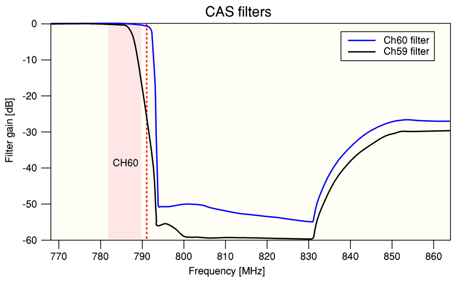
Back in the days when TV was ‘analogue’ each UHF channel carried just one TV station in a given area. So when changing from BBC1 to BBC2 people would say they were “changing channel”. We took for granted that ‘channel’ also referred to which TV station we wanted.

But with digital TV we now get groups of TV stations, all bundled together so they can arrive in a single UHF channel. This gives us many more TV and sound radio stations. But, as a result, in many areas UHF ‘channel 60’ will actually be delivering BBC1 and BBC2 and a number of other BBC TV and radio ‘stations’. When you ‘tune’ your digital TV or recorder these days “changing channel” doesn’t mean what it used to in analogue TV days!

So if the 4G interference blocks your ability to get UHF ch60 you will probably lose BBC1, BBC2, BBC3, BBC4, etc, along with the main BBC Radio 1, 2, 3, 4. etc. In other areas the block of TV/sound radio stations you’ll lose will be different. But note that UHF ‘ch60’ or ‘ch59’ doesn’t mean what you get when you press ‘60’ or ‘59’ on your TV remote control. It will probably means many TV and sound radio stations with various numbers in your TV guide!


The root of the problem posed by continued use of ch60/60- is that it demands a filter than can transit from passing signals to rejecting them in a very narrow transition range. The graph above illustrates the difficulties when we compare the two designs. The ‘ch60 filter’ is aimed at situations where ch60 is being used. This means it has to pass the ch60 DTTV signals with low loss and avoid excess tilt in amplitude or phase across the channel that would, itself, degrade the receiver’s ability to operate. Since the LF end of the 4G band is only about 1 MHz away, the result is poor 4G rejection for frequencies in the lowest few MHz of the 4G band. It also leads to relatively poor rejection across the rest of the 4G band. Even well into the 4G band the rejection is only in the range from 25dB to 30dB. The example I used earlier as an illustration of the situation that may be common produced a 4G level from the domestic DTTV antenna in the range between 100 mV and 200 mV. In such cases the ‘ch60’ would reduce this to being 3 to 10 mV. Given a domestic DTTV RX that rejects efficiently, a DTTV output from the domestic antenna around 3-5 mV may allow satisfactory reception. However it is worth reminding ourselves that this example is one where the DTTV RX system is 400 metres from the 4G base station radiating the (assumed) challenge. Many people will live closer than this, and be exposed to higher 4G levels.

For those living in a location where DTTV does not require the use of ch60/60- for TV the situation improves. This can be seen by considering the ’ch59 filter’ which is a design aimed at such circumstances. Because this filter does not need to ensure that it passes ch60/60- it can employ a wider transition and achieves around 35dB of rejection, being around 25dB even at the LF edge of the 4G band. This would cut the above down to around 1·5 - 3 mV, which may well be a useful improvement in many cases.

Fig11.png - 30Kb

Figure 11

Figure 11 shows the results for the second type of filter considered. These are aimed at communal systems. They have markedly better performance that the ‘domestic’ type. I assume the argument here is that a communal filter can be more expensive because the cost is spread across a number of households. However it is worth noting at this point that many ‘non communal’ households these days employ a distribution amplifier. This is typically somewhere like in the loft. These add an extra layer that may require protection from 4G signals. Otherwise they may generate intermodulation that makes it harder for the following TV receivers to read the wanted DTTV modulation. Given this, it may be worth wondering if filters to the above ‘CAS’ standard may be required in some – or many – single-household dwellings. As with the domestic filters, though, it can be seen that being able to discard ch60 provides a clear improvement in filter performance.

Some ‘4G filters’ have already come onto the market. So people can now choose to buy them if they wish. However the promise made by OfCom and the 4G companies is that suitable filters will be handed out, free. And it is far from clear how well any of these filters may work, or how likely they will be to solve the problem in any particular case. So anyone buying at present should bear in mind that it may not be needed, may not help, and a free alternative might be available. Time will tell...


Snags and desirable changes?
The above shows a situation where two filter profiles for each class of application (domestic / CAS) are being considered. To me, this looks like a clear sign that the assumptions being made should be questioned. If we take a step back it becomes clear that the driving assumption which leads to more than one filter profile is a decision to only have a tiny guard gap between DTTV and 4G. A need to have two profiles is Nature’s way of telling us that 1 MHz is impractically small! The outcome is then an increase in costs and complexity for the filtering, and added complications for the distribution of the filters.

It seems to me that it would be more sensible to have a wider frequency gap between DTTV and 4G. This could most simply be done by one of the following changes to the plans.
  1. The DTTV mux allocations could be arranged so that ch60 is unused.
    or...
  2. The 4G allocation’s LF limit should be shifted upwards by a minimum of 5MHz.

i.e. someone should sacrifice a channel to provide a wider gap, making effective filtering more practicable.

Either of these options would significantly ease the filter design requirements and help establish a situation where a single filter profile would be sufficient and deliver improved results. The drawback of option (1) is that the broadcasters, etc, would have to sort out being able to cover the UK with one more lost channel. The drawback of (2) is that the 4G providers would lose some spectrum allocation. But the outcome would probably be more satisfactory for TV distribution, and probably reduce the costs for consumers in terms of factors like the increased cost of future sets, reduced problems with domestic equipment moved from one area to another, etc.

Given the ‘polluter pays’ principle, it would seem to me to be that the onus should be on on option (2) by default unless option (1) is clearly feasible and does not pose a significant difficulty to TV coverage. However in my view, either option would yield a much more satisfactory situation than the current plan.

An alternative would be some form of hybrid arrangement. If the broadcasters have to go on using ch60/60-, then such areas should have a guarded status. In – or near – such DTTV coverage areas the 4G provision either would either exclude the region below, say, 795MHz, or only use this with significantly reduced EIRP levels. The requirement in such guarded areas is that 4G provision would be required not to affect DTTV reception given standard filtering. Unfortunately, such a hybrid would probably end up being unsatisfactory all round – as tends to be the case for most ‘political fudges’. So my personal view is that either of the simple options (1) or (2) above should be adopted as the cleanest approach.

Even if one of the above options were implemented there are some other serious drawbacks with the ‘mitigation filter’ proposals I’ve read. In particular – presumably in an attempt to limit the cost to 4G’s ‘MitCo’ the idea that only one filter per household will be provided for free. (And even this is shaved back with added exclusions, etc.) The glaring problem with this stems from the same difficulty I referred to earlier. That such a ‘one off fix’ may lead to problems later on, and ‘MitCo’ may then wash their hands of the consequences. I can illustrate that with a fairly simple example...

Consider an affected household with one DTTV set connected to an external antenna. For simplicity I assume there are no amplifiers or other equipment. In such a case the optimal location for an added 4G protection filter is at the UHF input socket on the back of the TV set. That ensures that interference picked up by the UHF downlead as well as by the antenna will be filtered. The result may be fine on the day the filter is installed. But what happens a few years later when the family move, taking their TV with them? It seems quite likely they’ll take the filter as well, assuming, ‘We may need that’, or simply regarding it as a part of the TV they own. Those moving into the house will find the antenna and downlead. But no filter, and perhaps no immediate sign that one is needed. They plug in their own TV, and find they have reception problems! You can think of various quite plausible scenarios that lead to the same kind of outcome. Given millions of households, it will be happening every day.

The problem here is that 4G won’t just be emitting signals that will upset TVs on day one when filters have been (we hope!) handed out. It will go on into the future emitting them. Until essentially all DTTV receivers have their own internal filtering (at increased cost to the consumers) such problems will keep arising. Again, under the ‘polluter pays’ principle we might expect MitCo/4G to go on handing out filters, for free, to affected homes for many years. But is this going to happen? Or will the problem be dumped onto consumers who move home and find they are out of luck?

As things stand, it looks to me that many people will be adversely affected by 4G, and that there will be ongoing detrimental effects that won’t adequately be solved just by a filter handout at the introduction of 4G. An aggravating factor is the combination of the high levels 4G will produce within half a km of their base stations and the unwisely narrow guard gap. Another is the perception that a ‘day one fix’ will be all that is required. In my view, both these issues need more urgent attention before 4G starts using the band above ch60. But I’m not holding my breath...

If you want to discover if your area is one of those most likely to be affected by interference from 4G, have a look at the maps on this page.
Jim Lesurf
5600 Words
27th Feb 2013

[1]  Technical analysis of interference from mobile network base stations in the 800 MHz band to digital terrestrial television. (Further modelling) OfCom Technical Report 23 Feb 2012 http://stakeholders.ofcom.org.uk/binaries/consultations/949731/annexes/DTTCo-existence.pdf


ambut.gif - 3891 bytes