Bass Performance of the Quad FM4
During the last year or two I have heard occasional comments expressing the view that the Quad FM4 tuner lacked bass output. A recent thread on uk.rec.audio brought this topic up again, and gave a URL for a webpage. This prompted me to investigate as I have an FM4 and it does not sound particularly lacking in bass to me, nor do the published specs or review measurements on the tuner indicate a lack of bass.
The webpage at http://www.fmtunerinfo.com/shootouts.html#FM4 describes a number of “shootouts” (sic) or comparisons between various tuners. The comparison between the FM4 and another tuner includes the statement:
“The sound? The FM4's midrange was open and airy without being thin or too light-sounding. I sensed that this tuner reproduced all the resolution each station was capable of giving. The highs were a touch forward, but never unpleasant. The problem was in the bass, or lack of it - and not just compared to the big, boss bass of the L-02T, either. The Quad's bass seemed more rolled-off than many tuners that have gone through the Shootouts.”
However reading the rest of the webpage I also found the following comment near the top of the page:
“The tuners under test see a Creek A/B switcher's 18 K ohm input. The Creek sees the line stage's 250 K ohm input. Some tuners with very high output impedance may have some bass rolloff. ”
Now the specifications for the FM4 which Quad gave in their literature includes a requirement that the recommended output load presented to the tuner must be greater than 20 kOhms. Since the test conditions employed for the above “shootout” fail to conform with this specification the tuner was not being used in accord with the conditions of use for which it was designed. Given this, it is perhaps not surprising if it did not perform as Quad intended. Unfortunately, the webpage omits to mention that they are testing the tuner in conditions which are not in accord with what Quad specify. It is also perhaps slightly misleading that their comment above refers to “very high output impedance”. A high output impedance, if resistive, might lead to a reduction in level at all frequencies if a load with a low resistance is employed. It would not necessarily produce a specific reduction of bass.
The Quad FM4 was designed and marketed some years ago, and I suspect that Quad assumed that it would mainly be used with their own pre-amplifiers — e.g the Quad 34. At that time it was common practice in the UK for preamps to have input impedances of the order of 100 kOhms for line level or ‘radio’ inputs, and the Quad 34 conforms with this practice. This implies that Quad actually assumed that users would be presenting a load more like 100 kOhms than 20 kOhms to the FM4, and designed the FM4 on that basis. To investigate the effects of load impedance on the FM4 we can examine the circuit diagram.
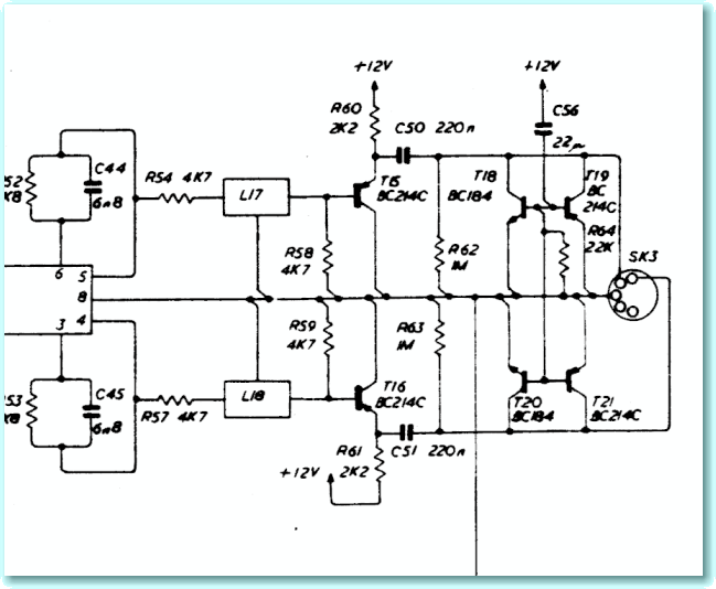
The diagram above shows the output section of the FM4’s circuit diagram. (The diagram shown is for an issue 1 board, but the details are essentially the same for later issues.)
The output comes from an TCA4500A stereo decoder IC (mostly out of view on the left) and each channel is passed through a Toko multiplex filter (L17/18). It then passes through an emitter follower buffer (T15/16) and then via a d.c. decoupling capacitor (C50/51) to the output terminals. Output capacitors are required because the circuity is powered from a single-rail, hence a d.c. voltage is present at the outputs of the buffer transistor. This must be removed before the audio can be presented to the output.
The arrangement of transistors, T18-T21, is employed as a mute circuit, but can be ignored here as it plays no part when listening because these transistors all act as open-circuit switches during listening.
The most significant aspect of the output arrangement when considering possible ‘bass light’ results is the value of C50 and C51. These are shown as 220nF capacitors in all issues of the circuit diagram. Looking at the diagram it struck me that this is quite a small value for such a location. These capacitors form an RC high-pass filter when taken in conjunction with the impedance presented as a load to the output terminals.
Strictly speaking, the load impedance is seen in parallel with R62 or R63. In most practical cases, though, the load when a preamp is connected will be well below 1MOhm. For that reason I decided that the values of R62/63 are high enough that we can ignore them here.
In general, the power-frequency response of such an RC network is given by the expression
where
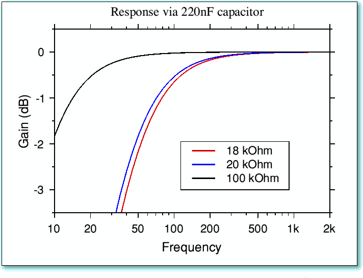
The graph below indicates the low-frequency response this output/load network will produce for three choices of load resistance.
Looking at the above we can see that – provided we have a load resistance of 100 kOhms – we can ensure that the response only drops by around 0·5 dB at 20Hz. However if we reduce the load to the absolute minimum value of 20 kOhms which Quad permit, the response at 20Hz is down by more than 6dB, and the -3dB point is at 36Hz. An even lower, 18 kOhm, load causes the response to fall to -7dB at 20Hz and gives a -3dB point of 40Hz. These values omit any additional band-limiting due to other stages in a complete audio system. Although a matter of judgement, I think it fair to say that the curves above serve to indicate that we should take Quad’s recommendation seriously if we wish to avoid a significant reduction in the level of low bass. For that reason I feel it is inappropriate to test the FM4 with loads of 20 kOhm or less without clearly warning this is the case. Otherwise the results may be quite misleading for anyone who would be using a preamp with an input impedance more in accord with Quad‘s expectations and recommendations.
Notwithstanding the above, it is debatable if it was a wise choice for Quad to use such a small value as 220nF for the output decoupling capacitors of the FM4. Lack of awareness of the implications of this choice, combined with the failure of some users to ensure a suitably high load impedance, plus reports like the “shootout”, may explain the reputation the FM4 has gained with some people. This is perhaps unfair given the nature of the effect described here, since it stems from using the tuner in conditions Quad did not intend. On the other hand, Quad might have been wiser to have used larger values, or give a more specific warning/information about this point. Ideally, the problem may be avoided by ensuring a load impedance of at least 50 kOhms, and preferably around 100 kOhms. Alternatively, the problem might be amenable to a change of the relevant capacitance values where use with a low impedance load is unavoidable – although of course any such modification would not be something that Quad might sanction.
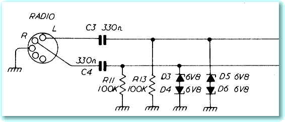
When using the FM4 with the Quad 34 preamp we can expect the load impedance to be 100 kOhms. However this may not be the whole story as we can see by examining the diagram below.
This shows the section of the circuit diagram of the Quad 34 that takes the signals from the ‘radio’ input socket. Note that although R11/13 define a nominal input resistance of 100 kOhms, the input for each channel also passes through another d.c. break capacitor. The value of these capacitors (C3/4) is 330nF. (The above is, again, taken from the issue 1 board, but is essentially the same in later issues of the Quad 34 circuit.)
Now so far as the audio signals are concerned, these capacitors are in series with those in the tuner output stage. The result is a total d.c. break capacitance in each channel of
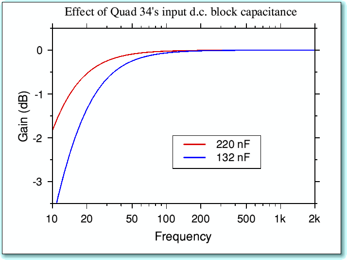
As a consequence, if we continue to neglect the 1MOhm resistors in the tuner, the response when we use the FM4 with the 34 is not quite as indicated by the 100 kOhm line in the previous response graphs. Instead, it is as shown below when we assume a capacitance of just 132 nF.
The result is now around 1·3 dB down at 20Hz, and the -3dB point produced by the capacitor combination is at 12 Hz. This is perhaps a modest bass roll-off when compared with the effects of, say, most loudspeakers. However it may be enough to be of some significance – particularly in comparative tests rather than in normal use.
I am not sure to what extent a droop of 1·3 dB at 20Hz would be noticeable in normal use. Given the effects of most loudspeakers and room acoustics, and bearing in mind that any test comparisons on tuners which used the 34 preamp would apply the 330nF input cap to both tuners, it is questionable if this would be easily noticed. However it may perhaps have contributed to a reputation for a lack of bass. My personal view is that the FM4 is best used with a high impedance load, and if this is done, any bass loss may not be significant. However I must admit that if I had designed the FM4 I might have used larger values for the output caps!
I would like to thank Tony Sayer and John Philips for prompting this analysis and making useful comments.


