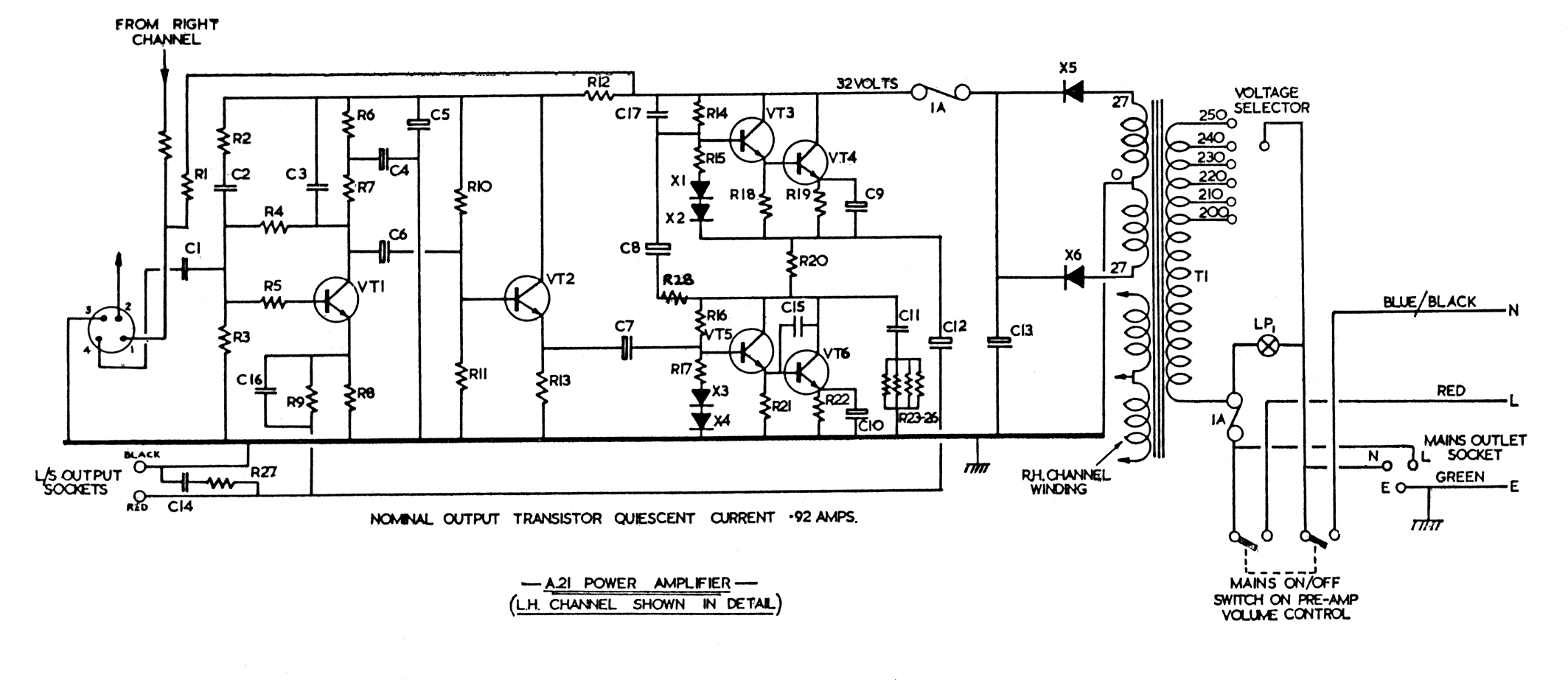
| For the Richard Allan version of the A21 the components used were as listed below. | |||
| R1 = 4·7k | R16 = 2·7k | C3 = 470p | VT1 = BC108 |
| R2 = 1M | R17 see Note 2 | C4 = 80, 25V | VT2 = BFY53 |
| R3 = 220k | R18 = 100 | C5 = 80, 25V | VT3 = BFY52 |
| R4 = 1M | R19 see Note 2 WW | C6 = 25 | VT4 = BD151 |
| R5 = 4·7k | R20 = 1·5, WW | C7 = 400, 16V | VT5 = BFY52 |
| R6 = 1·2k | R21 = 100 | C8 = 80, 25V | VT6 = BD151 |
| R7 = 4·7k | R22 = see Note 2 WW | C9 = 80, 25V | X1 = BAX13 |
| R8 = 47, CF | R23 = 10 | C10 = 4000, 2·5V | X2 = BAX13 |
| R9 = 1k, CF | R24 = 10 | C11 = 0·1 | X3 = BAX13 |
| R10 = 5·6k | R25 = 10 | C12 = 2500, 40V | X4 = BAX13 |
| R11 = 2·7k | R26 = 10 | C13 = 2500, 40V | X5 = 1OC1 |
| R12 = 680 | R27 = 1, WW | C14 = 0·1 | X6 = 1OC1 |
| R13 = 330 | R28 = 10 | C15 = 470p | |
| R14 = 2·7k, CF | C1 = 0·1 | C16 = 2200p | |
| R15 see Note 2 | C2 = 0·01 | C17 = 470p | |
|
Resistances in Ohms and Capacitances in microfarads unless otherwise indicated.
Note 1: Resistors are 0·5W 10% except those marked CF which are Carbon Film 2%, and those marked WW which are wirewound 10%. Note 2: R19 and R22 are selected from 1 Ohm 10%, R15 and R17 selected as follows: R19 and R22 in range 0.90 - 0·95 Ohms, then R15 and R17 = 220 Ohms R19 and R22 in range 0·95 - 1 Ohms, then R15 and R17 = 240 Ohms R19 and R22 in range 1 - 1·05 Ohms, then R15 and R17 = 250 Ohms R19 and R22 in range 1·05 - 1·1 Ohms, then R15 and R17 = 270 Ohms. Note 3: X1+X2, X3+X4 selected to give combined forward voltage drop of 1·38 volts (cold) at 4mA. Note 4: VT4 and VT6 are a matched pair. | |||