When investigating loudspeaker cables I came across various methods which people use to assess their behaviour. One is the use of squarewaves or other waveforms with abrupt ‘steps’ or pulses. If you look at audio magazines from a few decades ago you can see that back then squarewaves were routinely used as a test waveform for various purposes. But in more recent times they have largely disappeared from reviews. So what’s the story behind this change? What are the reasons for the fall in their popularity?
Figure 1
Figure 1 shows two waveforms. The red line is a perfect +/-1 Volt squarewave with a frequency of 5 kHz. One of the features of a squarewave is the abrupt changes in level. The waveform voltage should regularly jump by 2 Volts. In theory, these jumps should take no time at all. i.e. an infinite rate of change during each discontinuity. This requires the waveform to have a spectrum with harmonics of 5kHz reaching right up to infinite frequency.
Figure 2
The red lines in Figure 2 represent the spectrum of such a theoretically perfect squarewave. Here I’ve only displayed up to 1 MHz, but you can see that even at that frequency the harmonics of a 5 kHz squarewave are only about 45dB down compared with the fundamental component.
The behaviour of all real-world signal sources, amplifiers, etc, are limited by various physical effects that prevent them from generating signal levels that change infinitely quickly. Indeed, basic physics and information theory tell us that in analogue systems such discontinuities are impossible. The physical reasons for this depend on the circumstances, but one obvious example is that all real electronic components have a non-zero capacitance. To change the voltage across a capacitance we have to move charge from one place to another. This means that an infinitely fast change in voltage would require an infinitely high current!
If you had a keen interest in audio a few decades ago you may recall the phrase ‘Transient Intermodulation Distortion’ (TID or TIM). This is an effect which may be prompted by rapid changes in signal level that amplifiers or other items of equipment struggle to reproduce. The response can be a behaviour called ‘Slew Rate Limiting’ where the amp changes (slews) its output voltage as quickly as it can. This produces an output where any fast changes adopt a bevelled appearance when looked at on an oscilloscope. While slewing, the output loses any details of the input waveform while amplifier desperately tries to keep up – and fails! The result can be a nasty form of distortion. However these days you don’t hear much about TID. This is because there are some fairly simple solutions which can virtually banish the problem from domestic audio systems when they are used as intended.
Figure 3
Figure 3 illustrates how this can be done, using the example of a preamplifier and power amplifier. Each amplifier includes a resistor and capacitor at its input, arranged to act as a passive low-pass filter. I’ve outlined these in the diagram using rectangles drawn with broken red lines. These input filters define the bandwidth of the signals which can reach the actual active parts of each amplifier. There may well also be an output network fitted to the power amp. I’ve shown this inside a broken green rectangle, but for now let’s ignore the output network and assume the amplifier is connected directly to the loudspeaker load.
If we take an example where each RC filter is chosen with a -3dB point at 100 kHz then the nominal frequency response of the pre/power amplifier pair would be as shown in Figure 4. This represents a pre/power amplifier pair whose response is just -0.35dB down at 20 kHz. (i.e. the pre and power amps measured separately would be less than -0.2dB down at 20 kHz.) I’ve assumed the amplifiers provide a combined voltage gain of x40 at low frequencies. This means an input of +/-1 Volts will produce an output scaled up to +/-40 Volts. I chose this value because a sinewave whose amplitude is 40 Volts into an 8 Ohm load delivers about 100 Watts, hence it represents a typical level for a reasonably powerful amplifier.
If we now apply an almost perfect 5kHz squarewave to the preamp’s input the result appearing at the output of the power amp will be shaped like the blue line in Figure 1. The amplitude is scaled by x 40. The change in waveform shape isn’t due to nonlinear distortion. It is the result of the filters reducing the amplitudes of the high frequency components in the waveform (and altering their phases). The blue lines in Figure 2 show the spectrum of the signal emerging from the power amplifier, scaled to the same amplitude as the input squarewave. By comparing the input (red) and output (blue) spectra in Figure 2 you can see that the filters in the amplifier significantly reduce the levels at ultrasonic frequencies reaching the output.
Figure 4
Overall, one effect of the input filters is to define the maximum rate of output voltage change we will demand from the amplifier for any input signal. Of course, we could wind up the amplitude of the input waveform, but there is a limit here also because if it becomes too large the amplifier output will clip. So we can now choose input filters to arrange that even the largest possible waveform that does not clip the amplifiers should only require a rate of change of output voltage they should be able to provide without TID.
Figure 5
Alas, this isn’t the whole story. To understand why, lets look at what output current is required for two types of output load, one a resistor and the other a capacitor. Figure 5 shows the current the power amplifier has to supply if we use a squarewave generator for the input and produce an output waveform which swings between +40 and -40 Volts. You can see that with an 8 Ohm resistive load the required current is just +/- 5 Amps and the shape of the current waveform is the same as the output voltage waveform. However if we use a 2.2 microfarad capacitance as the test load – as was common in the past to represent a ‘difficult’ loudspeaker load like the original QUAD Electrostatic – then spikes appear in the current pattern, reaching up to +/- 40 Amps. This behaviour occurs because, when we have a capacitance as the load, the current required depends on the rate of change of the voltage. 40 Amps is a high peak current. However consider what we would have required if the amplifier designer had unwisely omitted the RC low-pass filtering...
It is quite easy to obtain and use test-bench squarewave generators with bandwidths well in excess of 1 MHz. i.e. to produce input signals with rates of change tens or hundreds of times higher than if they were bandwidth limited to 100 kHz. Using such a generator without any amplifier filtering might mean asking the power amp to output peak currents of many hundreds of Amps when the load is capacitive! As a result, when some engineers first started using such squarewave generators and difficult loads it became easy to over-drive some power amplifiers and prompt them to distort during the periods of time when the required rates of change and currents were very high. Problems like this were what lead to the flurry of concern some decades ago and hence the spectre of TID...
Fortunately, it soon became clear that this problem was more likely on a test bench than in domestic use. The reasons for this are obvious. Domestic audio sources aren’t laboratory squarewave generators, and recorded/broadcast music simply doesn’t produce signal patterns with such extreme bandwidths and rates of change. For example, CD Audio is limited to 22 kHz, and FM radio to 15 kHz. Even 192 ksamples/sec DVD-A is bandwidth limited to 96 kHz.
Figure 6
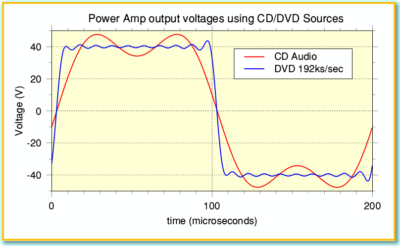
Figure 6 shows the output voltage waveforms we’d get from our pre/power combination if we used either a CD Audio or DVD Audio player as the signal source and played a disc of a recording of a 5 kHz ‘squarewave’. You can see that the actual waveforms aren’t very good squarewaves! Since CD Audio is limited to 22 kHz only the first two spectral components (5k and 15k) of the squarewave are present. The DVD-A does rather better as it can provide the harmonics up to a 96 kHz limit, but is clearly still not an ideal squarewave. For the sake of example I have assumed the players (and recording if appropriate) used time symmetric bandwidth filtering, and I have set the gain once again to provide +/-40 volts nominal output.
Figure 7
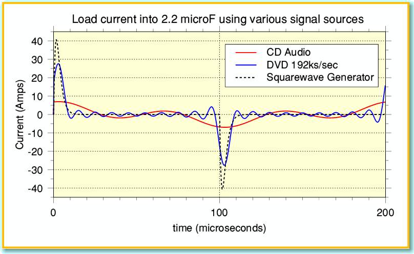
Figure 7 shows the resulting current patterns that our power amplifier has to provide if the load is a 2.2 microFarad capacitor. For comparison I have included the current plot when using a bench squarewave generator (shown by the broken line). Comparing Figure 7 with 5 you can see that when these domestic audio sources are used to playback recordings of a nominal 5 kHz squarewave the peak currents are much lower than if we’d used a good testbench squarewave generator. This is a simple consequence of the sources having limited bandwidths and illustrates the general rule that the lower the source bandwidth, the smaller the peak currents that may be required. The details will vary with the choice of source. They will also vary with the material that was recorded. In general, recordings and broadcasts of music don’t demand signal rates of change as large as the examples I have used. The problems apparent when using a squarewave generator are unlikely to show up in normal use, and can be almost completely prevented by the use of the input low-pass RC filters.
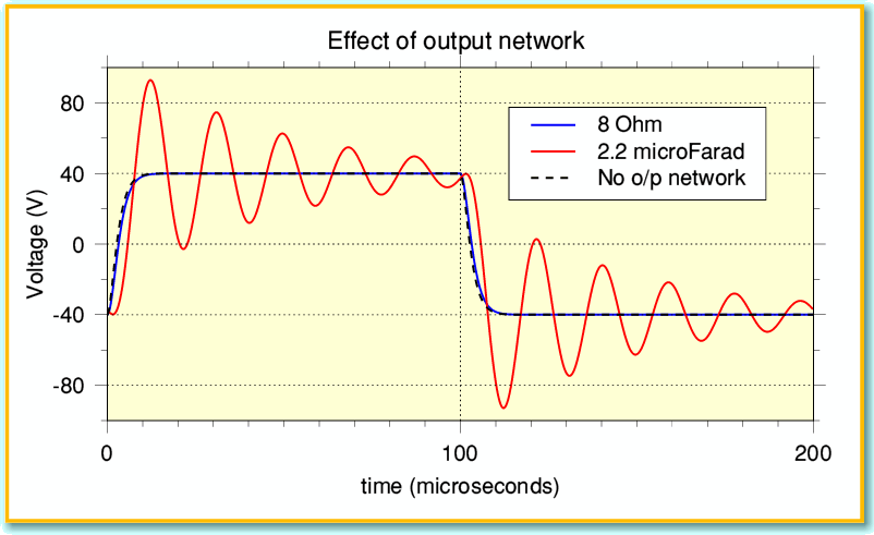
The remaining snag, of course, is that the beleaguered amplifier designed has no real control over the weird choices of load the user may then attach to the output of the amplifier. Given the variety of loudspeakers, and the wide choice of types (and lengths) of cables, almost any load is possible at high frequencies – as my investigation into cables has shown! For this reason many power amplifier designs include an output network with a series inductor as shown in Figure 3. This inductor acts as extra series impedance at high frequencies, and helps to prevent the power amp being presented with ultra-low impedances which might cause instability or demand large peak currents. Alas, as is usual in engineering, there is a drawback as illustrated in Figure 8. This shows the voltage patterns we get across a load with the same test waveform as before, when the power amp has an output network that consists of a 4 microhenry inductor and 10 Ohm resistor.
Figure 8
When the load is a moderate resistance the effect of the network is small. However when the load is a capacitance the effect is quite dramatic. The combination of output inductor and load capacitance tends to produce ‘ringing’ at a resonant frequency. In the past, reviewers would occasionally interpret this as a sign of amplifier instability. But it is simply due to the inductance and capacitance producing a passive resonance. Although it does look quite alarming the good news is that the actual ringing is well above 20 kHz. This means that is should not be audible. Also, although it may show up clearly when a testbench squarewave generator is used, when the source is a more normal audio item like a CD Player, FM Tuner, etc, the effect tends not to be present as their output has a more limited bandwidth that often does can’t excite the behaviour in the same way. You can see why by noting that the period of each cycle is around 20 microseconds. This is because the combination of the 2.2 microfarad load and the 4 microhenry output inductor produce a resonance at 54 kHz. i.e. well above the range produced by most domestic audio sources. And of course, most loudspeakers aren’t such a highly capacitive load.
Instrumentation engineers tend to call arrangements like the RC input filters and the LR output network Signal Conditioning. This is because they are used to define the range of signals and conditions which the amplifiers will be dealing with. In principle we can omit these extra components and have amplifiers that work without them. Provided the input signals and output load are as the designer intended the units can work well. The problem is that amplifier designers have no real control over the input signals and load conditions every user will impose. So the main purpose of including the filters/network is to provide peace of mind for both designer and user. They can also provide benefits in other ways – e.g. helping to block unwanted RF from mobile phones, etc, from entering into the amplifiers and disrupting performance.
So the main conclusion we can draw about the use of squarewaves as a test waveform is that the results produced need to be interpreted with caution. Firstly because the bandwidth of the test signal may matter, so a change of generator may alter the results. Secondly because domestic audio sources generally don’t produce such wideband signals or high rates of change when playing music or speech. Squarewave results may be useful for some diagnostics purposes, but need to be interpreted with care because the results can easily mislead or be irrelevant to normal use. This is probably the reason why squarewaves are rarely used these days by reviewers.
Jim Lesurf
2300 Words
January 2010


