HeadDAC-2 or “Son of HeadDAC”.
A couple of years ago I designed a simple headphone DAC I called the HeadDAC. This was aimed at being as simple as possible for someone to build with no previous experience of practical electronics. Since then I’ve been thinking about a new version that might provide improved performance, but still be cheap and easy to make. The result is the HeadDAC-2...
For newcomers to DIY electronics one of the most scary parts tends to be the need to put together a Printed Circuit Board (PCB) or to ‘embroider’ components and wires onto a plain board. To make things easier I decided to use a sneaky trick. I based the HeadDAC-2 on an existing PCB that you can buy as a cheap kit. It comes with the board, a bag of components, and a diagram to follow. It is also cheaper that the pair of small signal transformers I used for the original HeadDAC, yet it provides improved performance!
As a kit, the user can adopt a ‘painting by numbers’ approach. Each component in the circuit diagram has a number, and these numbers are also printed on the PCB. The idea being that the person building the kit doesn’t even have to understand how the circuit works. Just solder each component into the place shown. At least, that’s the theory...
The kit I chose is described as a Velleman ‘mini-kit’, and the PCB is just 5 x 6 cm square. It is called a “Super Stereo Ear”. It contains a pair of small microphones plus the components to make a pair of audio amplifiers to drive headphones. The purpose of the original kit is to act as a simple hearing aid for someone who finds the TV or radio (or conversation) hard to hear. Having looked at it, I must admit that I doubt it would work wonderfully well as a hearing aid. But that is because I doubt that the supplied microphones and a pair of normal headphones are ideal for such a task. However the board and components seem much more suitable as a basis of a headphone amp when fed by an audio DAC.
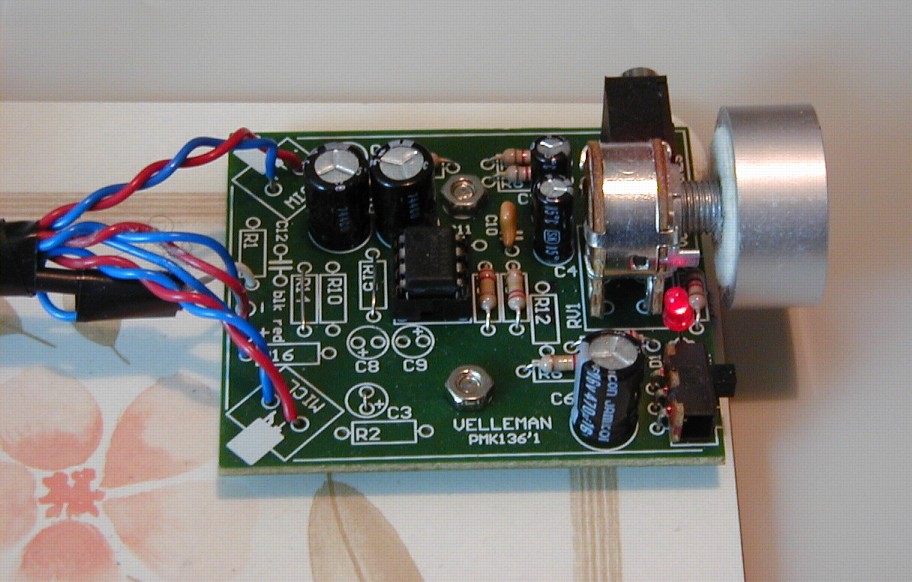
The above photo shows the board once I’d assembled it as a simple headphone amplifier and added a volume knob. You can currently buy the Velleman kit from CPC electronics. The CPC part number for the kit is HK00815 and it costs £7·19 (£8·63 inc. VAT).
If you look at the corners of the PCB you can see labels for two components ‘MICL’ and MICR’. This is where Velleman expect you to attach the microphones they supply. But instead I’ve taken wires to connect to the output of a small DAC. If you look carefully at the PCB you can see that I’ve omitted many of the components and in a few places replaced them with short wire ‘links’. (These links look silvery as they are tinned copper wire with no external insulation.) I have wired up the supplied on/off switch and a red LED that shows when the amplifier is switched on.
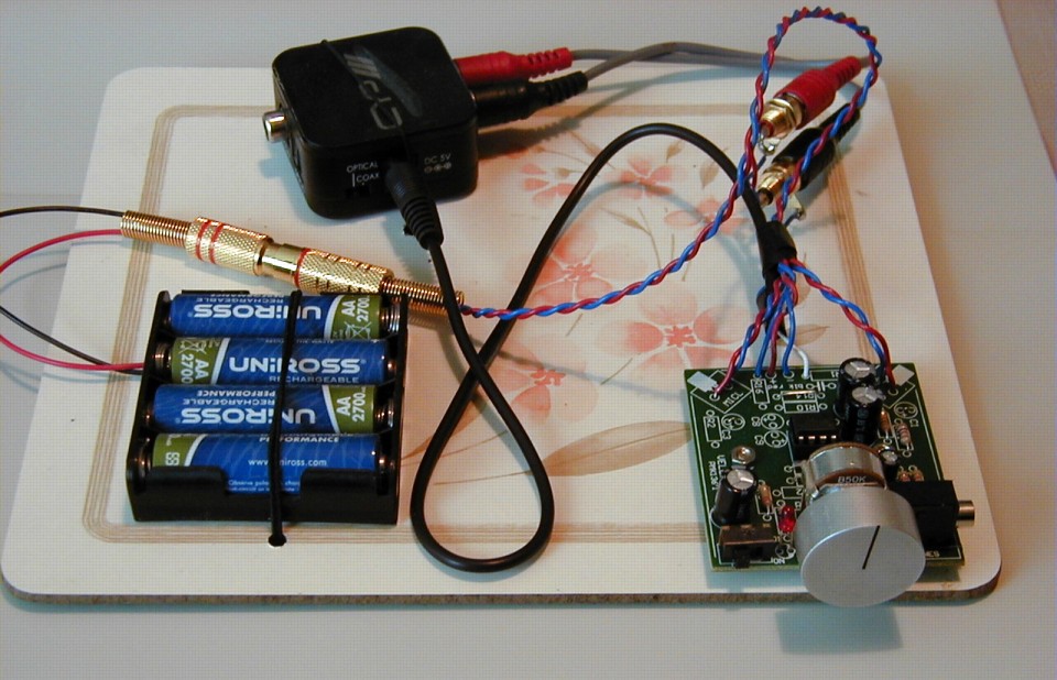
The picture above shows the headphone amplifier connected to a small DAC and their power supply. For low noise and simplicity I used the same DAC as I’d previously used for the original HeadDAC, and a power supply using a set of four NiMH rechargeable batteries. This provides about 5Vdc for the DAC and the headphone amplifier. This particular DAC only has Optical and Co-axial spdif inputs. But the same maker (CYP) also make one with a USB input. (And of course there are many other DACs around which you could use with the amp to drive headphones.) The Velleman mini-kit comes with a battery-holder for three AA cells. However I decided that I needed four NiMH cells to give a voltage large enough to power the particular DAC I had chosen. Having the higher voltage also allowed the amplifier to output larger signal levels. So I used a 4 x AA holder, also from CPC. Once the circuit was assembled I fitted a volume control knob which I already had. (Those with long memories when it comes to audio equipment might recognise it as being from an ancient Sinclair 2000 amplifier!)
You may have heard the term ‘breadboard’ used by electronic engineers when referring to a circuit they have just knocked together for experimental purposes. This actually stems from far-off valve days when some engineers would literally build their prototype on a wooden breadboard as it was insulating and easy to cut holes, screw down components, etc. Well, I didn’t use a breadboard as that is terribly old-fashioned. Instead I decided to use an old table-mat made of compressed paper! The Velleman PCB came with bolts and holes and little pillars to mount it. For the batteries and the DAC I used some lengths of elastic cord to tie them down to the place-mat! I doubt the result would win many prizes at a ‘High End Audio’ show, but at least it isn’t a boringly predictable silver or black box with buttons too small to find and legends too small to read.
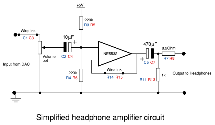
The diagram above shows the simplified circuit. The component numbers are the same as the ones given in the Velleman circuit diagram and printed on the PCB. There are two channels so each resistor or capacitor appears in two places. (Although there is only one NE5532 op-amp as the chip provides two actual amplifiers.) You can see that in some places an original component has been replaced by a wire link. Assembly is fairly simple, but I should say that the PCB and diagram I got in the kit did have a few errors. These don’t affect the above circuit if correctly assembled, though. The simplifications make the amplifier stage into a unity gain ‘buffer’. This doesn’t change the signal voltage but provides more current to drive power into the headphones.
The supplied gain (volume) control wasn’t ideal as it has a linear law. Good quality volume controls have a semi-logrithmic law. So I made one other modification which isn’t strictly necessary but make the amp easier to use. This was to add a 5k6 resistor between each volume control output and the ground (zero volts) wire. This ‘pulls down’ the shape of how the audio level varies as you rotate the control and gives behaviour more like a familiar volume control. Note that if you do this, make sure the DAC can happily drive a load as low as 5k. The CYP one I used seems quite happy, but this will depend on the DAC!
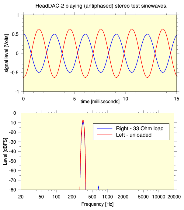
As well as listening to check the amplifier worked correctly I did some test measurements. The graphs shown above illustrate the resulting output. The input test signal was an antiphased stereo pair of sinewaves. One output channel (red line) of the headphone amplifier was left unloaded. The other (blue line) was connected to a 33 Ohm resistor to mimic headphones. Modern headphones general have a nominal impedance that is typically stated to be around 32 Ohms.
When tested, the amplifier showed it could output up to +/-0·5 Volts into a 33 Ohm load without clipping. The above shows this happening with a distortion level just above 0·01%. Loading the output does cause the level to drop slightly, as can be seen by the difference in amplitude between the channels. This is because of the 8·2 Ohm resistors in series with outputs of the NE5532. These are in place to help the chip avoid problems with reactive loads at ultrasonic frequencies, so I would recommend they be in place.
The measurements were made after some days of use following a recharge of the NiMH batteries. At that time the power rail voltage they could supply was about 5Vdc. A higher battery or PSU voltage would allow the amp to output bigger signals before clipping. But since I wanted to use the same batteries for the CYP DAC and the amplifier I didn’t want to let the power rail voltage exceed the maximum that 4 x NiMH AA cells could provide (about 5·25Volts).
The components for the HeadDAC-2 actually cost less than the ones required for the original design. This is because the Velleman kit costs about the same amount as just one of the pair of transformers required for the HeadDAC. In addition, you get the volume control and bunch of other components with the kit!
From a purely technical point of view, the HeadDAC-2’s performance is superior to that of the original HeadDAC. The earlier design employed a pair of cheap small-signal transformers to be able to drive headphones. These introduced a set of limitations that affected the technical performance. The main problems were that the transformers:
- Added quite a lot of series resistance, losing some of the signal power and giving the circuit a higher output impedance.
- Introduced nonlinear distortion.
- Limited the output at low frequency due to transformer saturation effects.
As a result, when we compare the original HeadDAC with HeadDAC-2 we find that the new design has a much lower output impedance and much lower levels of nonlinear distortion. It also has a far flatter frequency response, and can play up to 8 - 10dB louder. Modern headphones vary quite a lot, and to be honest their published specifications are often less than helpful. But typically they have claimed sensitivities above 110 dBA/Volt. On that basis the HeadDAC-2 should be able to play music at levels up to about 100 dBA, which I suspect is loud enough for most people! But maybe there will be a HeadDAC-3 one day to cater for those who want more...
1600 Words
Jim Lesurf
31st Oct 2012