OK, people who speak “American English” tend to call these “tubes”. However I’ll use the word “Valve” as
- I am British and (almost!) speak “English” rather than “American”.
- It’s simpler than calling them something like “Vacuum-state Thermionic Devices” all the time!
Thermionic Emission
Metals at room temperature have a lot of electrons inside them which can move around in response to an applied electromagnetic field. However under normal conditions the negative charges on all these electrons are cancelled out by the positive charges on the atoms of the metal.
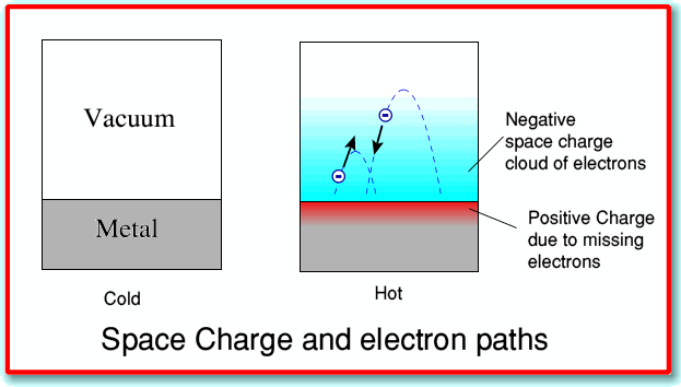
If we heat up the metal, however, we give the electrons more kinetic energy. This may mean that some have so much energy that they can ‘leap out’ of the piece of metal into its surroundings. However when they do this the metal, having lost an electron, now has a positive charge. The result is an electrostatic attraction between the (negatively charged) electrons that have leapt out of the metal and the (positively charged) metal they have left. This tends to pull them back.
The result of the above is to produce what is called a “space charge effect”. The hot metal becomes surrounded by a “cloud” of electrons, that have jumped out of the metal, but are then drawn back by the attraction between the electron and the metal. Taken overall, the system is still electrically neutral since we have the negative electrons and the positive metal. Add their charges and we still can get zero. It is just that some of the negative charge is ‘displaced’ from the metal to its surrounding. In this case, if we heat one of the metal pieces of our diode valve it becomes surrounded by this space charge.
The usual practice with valves is to use the heated metal as a cathode – i.e. as the part of the system that will supply electrons when we apply suitable voltages. Hence as you’ll see with the circuit symbols shown later, the cathode often has two leads. This allows us to pass a current though the cathode and heat it up.
The above explanation leaves out lots of details. For example, it is possible for some material surfaces to create a space charge around them even if we use them at room temperature. However here I’ll ignore such details as the valves that are used most widely do require the cathode to be heated for the valve to work.
The result is illustrated in the above diagram. When we heat up the metal we get a cloud of electrons that are ‘boiling’ off the metal surface and then (usually!) falling back again.
This property of ‘boiling off’ electrons is called ‘Thermionic Emission’ as the emission of electrons is produced by the heat.
Diode Valves
The easiest way to understand how valves work is to start with the simplest types and work upwards to the more complicated ones. The most basic was the earliest type that was invented. This is the Thermionic Diode. It basically consists of two parts or ‘Electrodes’, surrounded by an envelope which allows them to operate in a vacuum.
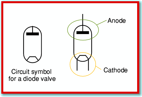
The standard circuit symbol for a diode valve is as shown above. (Please note, though, that the symbols may differ a little from one diagram to another, depending on the preferences of the person who drew the diagram!) The anode and cathode are made of good conductors (e.g. metals), but are separated by an insulating envelope and the vacuum inside.
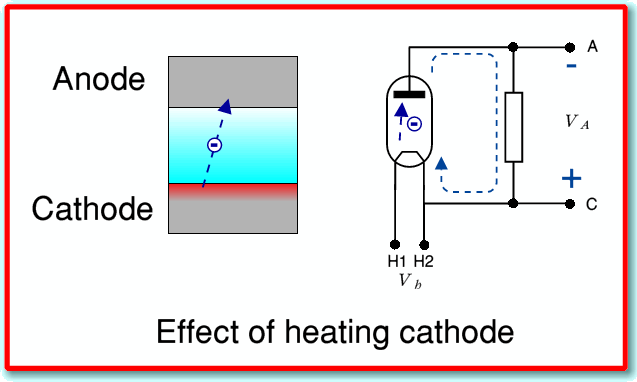
To start, lets consider connecting the diode up as shown below.
Here what we have done is heat the cathode by applying a voltage between the two cathode heater leads, H1 and H2. We have also connected the cathode and anode together via a resistor. If we do this we get a surprising result. We find that the anode develops a negative potential with respect to the cathode, and some current will flow through the resistor. Note that in this case the positive and negative signs shown on the above diagram don’t represent voltages we have applied from an external source. They indicate what the valve generates!
Unless we know what is happening inside the diode this result is puzzling as we seem to have created electrical power from nowhere and perhaps violated the law of energy conservation! Is this the solution to our global energy crisis and we can give up fossil fuels?... Afraid not. What is happening is that when we heat the cathode we create a cloud of electrons in the vacuum near the surface of the cathode. Most of these electrons will stay near the cathode. But a few will have energy to leap far enough from the cathode to be able to cross the vacuum and strike the anode.
Since the anode isn’t heated, it will grab any electrons that hit it, and they won’t have enough kinetic energy to escape it again. As a result a number of electrons end up sitting on the anode that have crossed the vacuum to reach it.
If we don’t connect the anode to anything, then as some electrons gather on the anode they give it a negative charge. This would tend to produce a negative potential, which then tends to repel any other electrons that approach the anode. Hence unless we give the arriving electrons some way to escape, they build up until they repel any further borders! However if we connect the anode back to the cathode via an external resistor, the arrivals can flow back ‘home’ to the cathode via the path through the resistor. As they do this, the anode potential relative to the cathode becomes less negative and some more electrons will have enough energy to cross the vacuum gap, thus continuing the flow. The broken blue lines with arrowheads in the above diagram show the direction of the electron flow. However note that for daft historical reasons we define ‘conventional’ current to be in the opposite direction to the actual electron flow. Thus in conventional terms we’d say a current flows through the resistor from C to A (positive to negative potential).
The energy which we see dissipating as the electrons pass through the resistor is part of the kinetic energy which they removed from the cathode when they were flung out of it by the thermal motions inside the cathode. Hence the energy is drawn from the heat we supplied to the cathode. Alas, no perpetual motion or energy crisis solution, since we have to supply energy to the cathode to drive this process.
The amount of current we’d see will depend on various factors. These include the temperature of the cathode, its surface area, the distance to the anode, etc. One of the most important of these factors is the details of the surface of the cathode. Most practical valves have cathodes which are treated or coated to enhance their ability to release electrons when heated. Despite this, with most practical valves, the actual current level we get if we carry out the above experiment tends to be very small. This is quite deliberate as in most applications we want the diode to have very low current ‘leakage’ when the potential difference between anode and cathode is around zero volts.
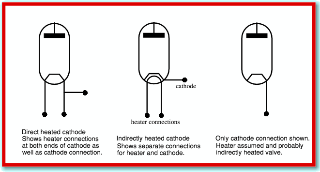
In practice it is also usual for a valve to have an ‘Indirectly Heated’ cathode. This means that the heater element is a wire inside the cathode, insulated from the external outer surface that acts as the electron emitter/cathode. This gives more flexibility in choice of materials, and also helps avoid any of the heater voltages or currents from affecting signals on the actual cathode. When we wish to represent the presence of an indirectly heated cathode the circuit symbol is altered as indicated below.
In practice it is fairly common to simply omit showing the details of the heater altogether. This simplifies circuit diagrams since the heater, and the wiring that powers it, can be assumed to be present with almost any normal valve used in electronic circuits. As a result many diagrams show symbols which look like the simple directly heated valve type, but are actually only showing the cathode, and omitting showing the heater. The giveaway for what is being represented is indicated above. In particular, if there is only one wire shown connected to the cathode we can assume that the valve is indirectly heated, but the heater wiring is being left off the diagram to make the diagram easier to read. Note that although the above shows diode valves, the same conventions tend to apply for other forms of valve such as triode, pentodes, etc.


