The Digits behind BBC FM


Audio fans often argue about the relative merits of ‘digital’ and ‘analogue’ systems, be they Vinyl LP versus CD, or FM radio versus DAB. FM in particular has often been presented as a superb example of the excellent sound quality an ‘analogue’ system can provide. However, although most listeners don’t realise it, the high quality of BBC FM transmissions owes a lot to digital systems developed and installed over the decades by pioneering BBC engineers...

Today we are so accustomed to digital audio, broadband, and developments like the BBC iPlayer that it is all too easy to forget that only a few years ago things were very different. Indeed, people may also forget when there was a time when FM wasn’t even in stereo, and for many listeners away from the South East of England, the sound quality was quite inferior to what we expect today.

BBC FM broadcasting officially began on 2nd May 1955 from Wrotham in Kent. This covered London and a large portion of SE England. During the rest of the 1950s a number of other FM transmitters were brought into operation. These rapidly established FM as the ‘high fidelity’ choice for radio listening. On the 13th and 14th of January 1958, experimental test transmissions in stereo took place from Wrotham. Later tests extended this to other FM transmitters around the UK. And by the end of 1958 these experiments became fairly routine. However even by 1966 stereo broadcasts were limited to around a few hours per week. Back then, a stereo broadcast was quite a special event for hi fi enthusiasts! Those of us who are old enough will remember the excitement on the rare and magical occasions when the ‘stereo’ indicator lit up on the front of our FM tuner!

TX1970.gif - 42Kb The map on the left shows the most powerful UK mainland VHF FM Transmitters in 1970. At that time stereo was only available on Radio 3. The other stations were mono only. Radio 1 didn’t even have its own FM transmissions. It had to share some of the Radio 2 provision on a part-time basis.

For the sake of clarity I have only shown the more powerful transmitters. But the pattern makes clear – even including some that take a feed from another, more powerful, transmitter – the limited geographical coverage for stereo.

The most populated parts of the South-East and Midlands were covered. But the rest of the UK was without Stereo radio. And the sound quality tended to deteriorate away from the South-East...

One of the biggest problems facing the BBC engineers and holding up a UK wide stereo service was the challenge of getting good quality stereo signals distributed to the FM transmitters. Although there were various special links, many of the connections were supplied by the UK’s State monopoly telecommunications provider of the period – The General Post Office (GPO). This was also the case for connecting outside broadcasts and venues to the BBC. They provided a set of standardised grades of landline for audio, and the BBC had to look to the GPO to get the audio from the studios to the transmitters.

The standard GPO “Tariff M Audio” provision was most often one of the following:
For longer distances the BBC could use a set of FM ‘subcarriers’ carried by a ‘vision’ circuit. i.e. a wideband link capable of carrying TV video was used to bear a set of FM signals to convey a number of audio channels in parallel, separated by subcarrier frequency. (This approach is known as frequency-division multiplexing or FDM.)

The problem was that all these analogue systems introduced signal distortions, added noise, etc. For example, although FDM had the advantage of allowing a number of audio signals (including pairs for stereo) to be carried as a bundle via the same route, it required FM modulators and demodulators, filters, etc. All of these had some effect upon the output. And any differences between individual modulators or demodulators could upset stereo quality.

The GPO landlines suffered from uneven frequency response (in phase as well as amplitude) and varied from one link to another. This meant that some quite complex equalisation was often needed to obtain a reasonable response, and the flat portion of the spectrum might cover a smaller range of frequencies than the above figures say. For stereo the situation was worse because it wasn’t enough just to have two lines. They also had to be closely matched, and equalised carefully, to get an acceptable stereo image.

As a result, what reached a transmitter ready to be broadcast tended to become more distorted and noisier, and the stereo poorer, as you went to locations further from Broadcasting House in London. In reality, the demands of realising the potential of VHF/FM stereo were almost impossible to achieve across the UK using the then-existing analogue technologies. But as often in engineering, necessity was the mother of invention, and the BBC engineers decided that digital was the way to crack the problem.


PCM Rollout across the UK
During the 1960s engineers at the BBC carried out research into the application of digital methods to audio and video. Experimental systems were tried out and a number of BBC research reports were published showing progress. On the 14th of September 1972 the link from Broadcasting House to the Wrotham transmitter switched to the new BBC PCM (Pulse Code Modulation) system. This produced a dramatic improvement in sound quality – even on the UK link that had already probably been the best performing. Radio 2 from Wrotham also officially started broadcasting in stereo from Wrotham on 4th November 1972. The new digital system now offered the prospect of the same high sound quality becoming available from the rest of the BBC’s main UK VHF FM transmitters, for Radio 2, 3, and 4.

In the November 1972 issue of Hi Fi News magazine Angus MacKenzie commented on the impact of the new PCM system.

“A year or so ago we [Hi Fi News] published some noise measurements made of the [stereo] test tones radiated from Wrotham on Radio 3, and it may be remembered that an approximate S/N ratio of only 58dB was average on each stereo channel... The PCM system is now giving a ratio from the output of the continuity desk [at Broadcasting House] to my own receiver of 65dB unweighted. Thus showing an improvement of 7dB over average conditions of the past. The improvement is noticeable mainly at the lowest frequencies with an almost complete elimination of all forms of hum... Although the crosstalk has usually been satisfactory the capability of the new PCM link is so amazing that at 900 Hz the transmitted crosstalk was measured in the early hours of Sunday 17th September and found to be 46dB (which includes the crosstalk of my tuner)... All these improvements have been noticed quite dramatically on relays of the last three Prom concerts... Those capable of receiving the BBC PCM [fed] stereo radio are almost certainly hearing the finest sound quality available in the world.”


It is important to bear in mind that these measurements didn’t directly represent the actual full performance of the PCM link. Other stages of the process that gets the audio from the source to the output of the listener’s FM tuner or radio would add noise, distortion, etc. But the measurements do show that, once the PCM came into use, the quality of what you heard when listening to something like a Prom on Radio 3 would mostly be limited by your local reception conditions, and the quality of your FM tuner. Angus used the outstanding Yamaha CT7000 FM tuner that was one of the FM ‘super tuners’ of the 1970s. But even with that and an excellent antenna his results were limited by factors like the VHF background noise around where he lived.

That said, for most listeners around the UK the main significance was that they could expect even greater improvements than Angus experienced if they had good reception and a decent tuner. Since other FM transmitters were fed via longer and more complex analogue routes than Wrotham, the quality of what they transmitted was often more seriously degraded by the time it got to the transmitter. Being fed using the BBC PCM overcame that. So the arrival of PCM would have a bigger audible impact for those using other transmitters away from London.

Initially the BBC intended to extend PCM to Sutton Coldfield within a month or so, and Holme Moss during the first couple of months of 1973. Unfortunately, although the PCM links were installed their coming into use was delayed. This was due to an industrial dispute between the BBC and the Association of Broadcasting Staff. The Association felt that operating the PCM links merited the operators having an uprated grading.

TX1982.gif - 39Kb However by the 4th of August 1973 Sutton Coldfield and Wrotham were both using PCM links to broadcast high quality stereo on Radios 2, 3, and 4. This in turn meant that some of their lower power subsidiary transmitters also then provided improved output, although sometimes degraded by having to pass along a non-PCM section for the last part of their journey to the transmitter. By the end of 1975, PCM stereo links had come into operation for many other UK mainland transmitters. With Divis (Northern Ireland) and Tacolneston joining the party by the middle of 1976. Various other links were converted at later dates reaching into the early part of the 1980s.

The diagram on the right shows the main PCM links for FM radio as they existed by 1982. (Some lower power transmitters are omitted to make the arrangement clearer.) By this time well over 90% of the population were covered by PCM fed FM transmitters.

The red lines show where ‘Vision circuits’ provided by the GPO/BT that were nominally designed for bearing analogue vision signals for TV use carried the PCM. The blue lines show where BBC radio links carried the PCM.

Each PCM audio channel could be individually employed as suited operations. So whilst some channels were used to distribute R2/3/4 for the VHF services from Broadcasting House, others could be used to send other audio signals from place to place. e.g. to AM transmitters.


The Original PCM system
The PCM system that was put into operation provided 13 independently assignable audio channels. So in principle this could support up to six stereo FM networks with another audio channel available if required. There was also a ‘14th channel’ – i.e. slots in the digital data stream for control/data signals – providing a way to remotely control transmitter operation. This gave Broadcasting House the ability to switch transmitters on or off. In practice this was a big advance on the previous system where they were switched on and off each day using a separate timer at each transmitter. These timers had to be set quite ‘generously’ to make sure they came on and the transmitter warmed up well before the first broadcast of the day, and then didn’t switch off until after transmissions ended for the day. (Yes, in those days, the programmes weren’t running 24 hours per day!) Another control signal allowed Broadcasting House to switch the stereo multiplex generators on and off remotely.

Each PCM channel was based on sampling the input analogue audio waveform at 32k samples/sec and generated 13-bit LPCM (Linear PCM) sample values. The sampling was dithered to suppress quantisation effects. The input to each analogue-to-digital convertor (ADC) was low-pass filtered to reject audio frequencies above 15kHz.

In principle a 13-bit linear PCM system should be able to provide a dynamic range (ratio of maximum clean signal to background noise) of the order of 78dB. In practice the background noise level will vary depending on the details of how the system is implemented. These days engineers concerned to totally remove unwanted effects like quantisation distortion or noise modulation would tend to add random ‘dither’ in a way that increases the noise level by around 3dB. The BBC PCM system used a more complex and ingenious approach that added less noise, but did expose the system to some low level effects. However given the noise and other problems in the rest of the chain (including the listener’s tuner!) that proved not to be a problem. One of the BBC engineers (S. R. Ely) did make measurements on the PCM encoder-decoder in 1978 and his measurements showed that the dynamic range it provided was, indeed, around 78dB or better. At the time this was better than any LP or Tape home hifi fans could obtain. Emphasising that from the establishment of PCM the BBC FM broadcasts at their best delivered ‘higher fi’ to the home than any other route.

For most listeners, performance was limited by their choice of FM tuner, and reception conditions. That said, the individual transmitters weren’t themselves upgraded when connected via PCM. So in some cases the actual FM transmitter electronics may have added noise or slightly degraded what the PCM supplied to them.

coderx.jpeg - 245Kb

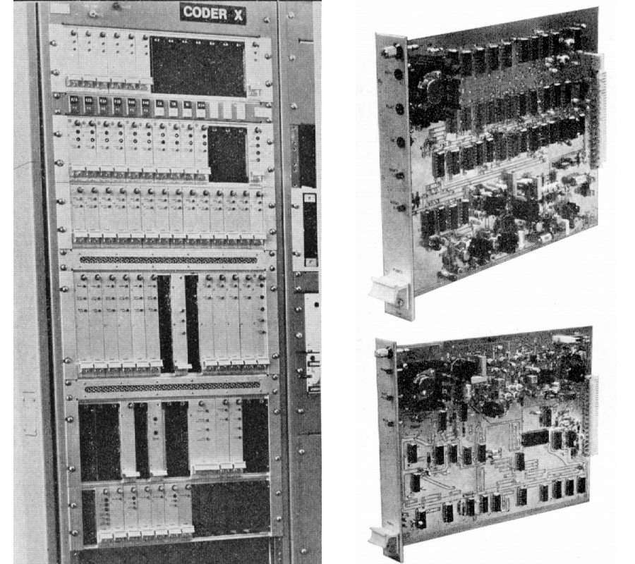
Coder X at Broadcasting House.                 Coder and Decoder Cards.


The above shows what the original equipment looked like. The left-hand image is one of the PCM (en)coder racks at Broadcasting House. The images on the right are of the coder (ADC) and decoder (DAC) cards for a single channel. (BBC Publicity photos) There were actually two complete PCM coders at Broadcasting House, labelled “Coder X” and “Coder Y”.

Today we tend to take for granted that devices like home computers, DVD players, and home theatre systems can easily handle stereo at 48k samples/sec or more, with at least 16 bits per sample. Serious high-quality home audio equipment can handle much higher rates and 24 or 32 bits per sample. The ADCs and DACs for this are made by the million, often integrated into a chip that also does other tasks. However things were very different forty years ago! Then it was a real challenge for BBC engineers to design and build a system that could reliably and accurately meet the 13-bit/32k spec. They had to develop this from basic components, and devise an ingenious arrangement as the simpler designs of the time simply couldn’t provide the required quality. The ADCs employed a dual-ramp-and counter design invented at the BBC. This gave more accurate and stable performance than other designs available at the time.

To optimise the performance for speech and music, the audio also had its frequency response shaped (pre-emphasised) using a standard CCITT filter before the ADC. This was then corrected to recover the original response after the digital-to-analog convertor (DAC) at the end of the PCM link. This process is essentially similar to the way in which FM transmissions have a ‘pre-emphasis’ applied which the receiver corrects to provide an improved dynamic range for speech and music. Peak limiters were also included in the coders that carried out the ADC conversion at the input end of the link. This was to avoid clipping or overloading. Where two PCM channels were used as a stereo pair, their limiters were coupled so that any brief reduction prompted by an excessive peak on one channel adjusted the gains of the stereo pair of channels in tandem. This avoided the stereo image ‘swerving’ to one side when a limiter caught an unintended signal peak on one channel of the pair.

codery.jpeg - 171Kb

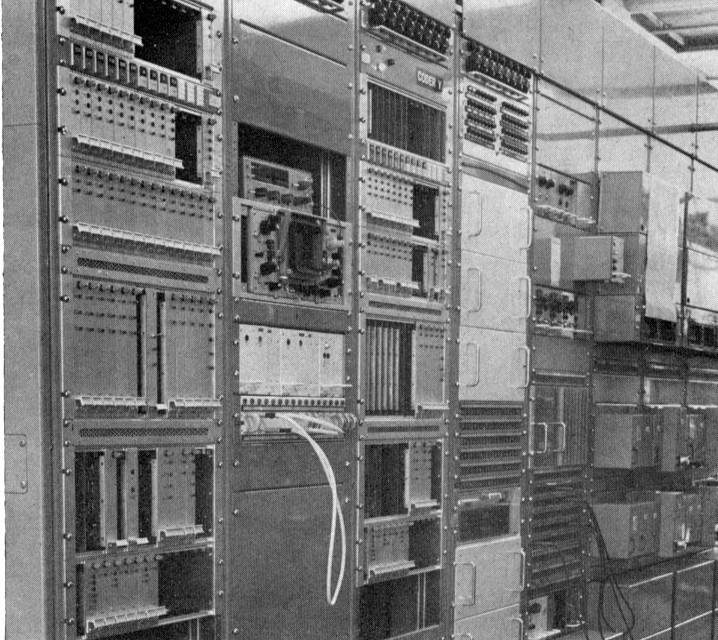
View of PCM coders at Broadcasting House.
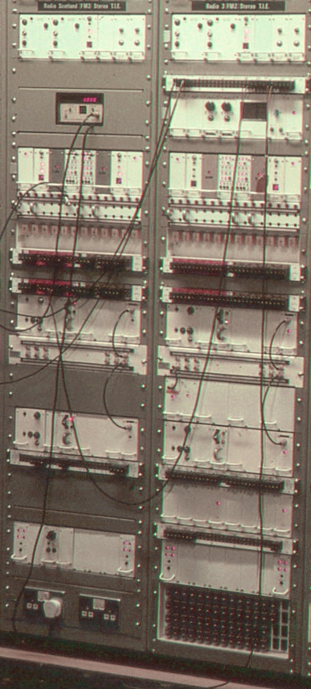
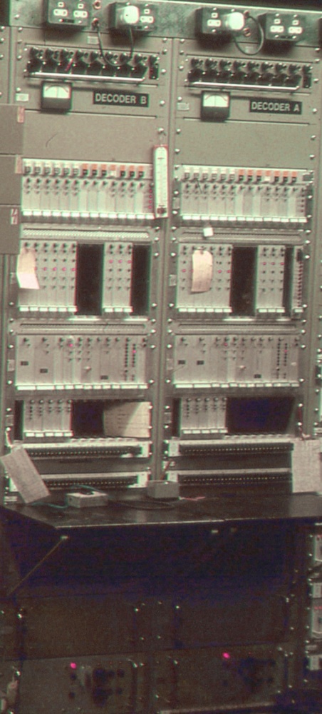

The above photo shows Coder X on the left, and Coder Y two rack bays to its right as viewed in the picture. In practice the choice of coder alternated day by day. This kept both in use and acted as a regular check that they were both in good working order. That in turn helped ensure that if one developed a fault, the other would be ready to take over.

GSPCM.jpeg - 163Kb GSTIE.jpeg - 201Kb
PCM Decoders
Transmitter Input Equipment
Photos kindly provided by Graham Sawdy


The above photos show some of the FM transmitter equipment at Sandale in 1978. The PCM decoder racks are shown on the left. Sandale then transmitted four FM services - Radio Scotland, and Radios 2, 3, and 4. The TIE (Transmitter Input Equipment) racks for BBC Radio Scotland and Radio 3 are shown on the right. (BBC engineers who can read ‘dasblinkenlighten’ on the front panels may be able to spot that one was transmitting stereo and the other mono at the time the picture was taken!) Note that there are two complete PCM decoders. Each TIE rack also contained two stereo encoders. Much of the equipment was duplicated in this way and were labelled as the ‘A’ and ‘B’ units. I'll let Graham Sawdy explain:

The PCM decoders were not used on alternate days as we heard that the BH coders were. There were less people on the transmitters than in BH to do this sort of thing - basically they were designed for fully unattended operation. The way it worked was that there were two completely duplicate chains, called A and B, right from the PCM decoders through the stereo coders and on to the FM drives (modulators) themselves.

The A/B drive changeover changed over the whole lot with an rf switch at the level of a few watts. The output of this was then split to feed the two parallel high power amplifiers taking the output to the final power level. All the A amplifier high power outputs were combined and connected by a feeder up the mast to one ‘half aerial’ the Bs were similarly fed to the other half. This meant that when one ‘side’ was off the power received by the listener was reduced by 6dB. 3dB coming from the halving of the power being transmitted and 3dB from the half aerial aperture giving lower aerial gain.

There was generally no reason to prefer either the A or B drive chain though one or other might be specifically chosen if, say, there was temporarily an intermittent fault on the other. The drives would be locked to A or B when work was being carried out on equipment on the other chain. Incidentally, this arrangement often meant that both PCM decoders were in service at the same time - if you wanted to work on one or the other you had to make sure all the downstream equipment was locked to A or B. Although it produced a slight click on the output, station staff felt free to make a drive changeover whenever necessary. The exception was Wrotham where staff were very wary - you could be pretty sure that whenever you did a drive changeover there, BH would be on the control line asking what the click was, because they were monitoring off-air.

By the way - I should point out that the various luggage labels were not a normal feature - the pictures were taken during commissioning!


GS337.jpeg - 148Kb
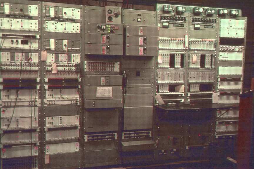
Wider view of the Sandale racks.
Photo kindly provided by Graham Sawdy.


The NICAM Era begins
Even while the process of installing PCM equipment was under way, the BBC engineers were carrying out research to develop improved techniques. This was driven by a combination of factors. One was the arrival of newer and better ‘bearer’ systems – i.e. ways to provide a link – that would be able to convey more data, more quickly, and be better suited to digital methods. The other was the wish for improved performance, more flexibility, and to cope with the increase in the number of BBC radio stations that was expected. This led to a desire that communications engineers are nowdays all too familiar with – the wish to squeeze a quart into a pint pot without compromising the results!

Various ideas were considered and tested. One of these was the Sound-in-Syncs technique devised for distributing mono audio to the TV transmitters. This converted the audio into a series of 10-bit PCM values, with a sample rate locked to double the line-scan frequency (i.e. 31·25 kHz). The series of bits was then inserted into the ‘flyback’ gaps, timed to fit inbetween the lines of the picture. The system allowed the analogue and video to be carried as one composite signal, and so simplified and improved performance. The snag was that, in itself, 10 bits per sample wasn’t really enough to give a satisfactory dynamic range. So a ‘compander’ system was employed. This had an audio level ‘compressor’ in front of the ADC, adjusting the amplitude of the sound to reduce the dynamic range to be converted to digital. An ‘expander’ was then used after the DAC at the transmitter to correct this and regain the original audio, restoring the dynamic range. In order to work, the compressor also generated a signal that indicated how much it was adjusting the level. This was then sent as a ‘pilot tone’ along with the audio and video, and used by the expander to know how to adjust the output correctly. BBC TV started using this system in 1971. It proved successful in UK, and was sold abroad for use by other broadcasters.

Experience with that system satisfied the BBC engineers that companding down to 10 bits per sample could work satisfactorily. But for FM distribution they wanted to develop an improved approach that exploited digital processing, and could generate a multiplex to carry all the required audio for radio broadcasting in one data stream.

NICAM stands for Near Instantaneously Companded Audio Multiplex. The system eventually used to provide digital feeds to BBC FM transmitters was called NICAM 3. A number of other NICAM systems were developed and used in various forms by the BBC for a number of applications. The different NICAM systems varied in detail. Early/experimental versions of NICAM (e.g. NICAM 1) sampled the audio using 13 bits per sample. But this was increased to 14 bits per sample for later systems like NICAM 3 and the NICAM system used to provide stereo audio for analogue TV broadcasting. However the ‘companding’ part of NICAM applied the same basic technique for all the systems put into use. It replaced the original use of analogue companding with a digital equivalent whose behaviour was better defined and more consistent.

A 32k sample rate had been judged to be fine for FM radio. However the increase to 14 bits per sample allowed for the nominal dynamic range to increase by around 6dB compared with the old PCM system. The 14-bit samples are gathered together in 1 millisecond blocks. i.e. 64 sample values per block for each stereo pair. The NICAM encoder examines these and identifies the highest sampled value in the block.

NICAM.gif - 53Kb


The diagram above illustrates the process, however I’ve simplified things to make the essential behaviour clearer.

For the sake of example, lets assume that the biggest value in a given block is, in binary, +110011 (+51). In this case, all the values in the block only need the 6 (least significant) bits to define their value (plus one more each for the sign). So having fourteen bits for each is wasteful. However in another block of sample values we may find that the largest value is +101100110010 (+2866). That would need the 12 (least significant) bits per sample for the value (and another for the sign). So the number of bits actually needed varies with how loud the music or speech may be during each 1 millisecond time block. The NICAM process identifies the subset of the bits required to ensure that the largest value is covered. It then takes 10 bits per sample, chosen to just meet that requirement. The result is as shown in the diagram.

The process is similar to the use of floating point values. But here the scaling for all the values in a block is the same. This means that we can remove four bits from every value (i.e. 256 for a block of 64 samples). Ii then also has to send one ‘extra’ value to indicate how many of the ‘least significant’ bits have been dropped from each sample in the NICAM block. The receiver (NICAM decoder) then uses this to pad the values with zeros where any bits were lost during NICAM transmission (coding).

Of course – except when the values are low – some details are lost in this process. For blocks where the audio signal is loud, the least significant bits of the sample values will be discarded. This produces a sort of ‘modulation noise’ which is typically around 55dB below the speech or music. The effect is low enough not to be particularly audible, but can be noticed. However extensive tests by the BBC showed that the audible impact of this was slight. Indeed, given how enthusiastic audio fans tend to be today about FM radio, four decades later, this judgement seems to be well justified by experience! The actual NICAM process is much more complex than I have outlined here. For example, the ‘Multiplexed’ part I have ignored completely. But the outcome was a system that could support more stereo radio stations over a wider choice of bearing / distribution systems, etc, and was very adaptable.


NICAM, Elton John, and Shanghai
The BBC engineers did a series of trials and experiments as they developed NICAM prior to it going into routine service as the backbone of BBC FM distribution. In the process they achieved some significant historic ‘firsts’ that have since, sadly, largely been forgotten. Yet they represented important technological achievements.

One such event was a live broadcast of a concert given by Elton John in the Rossyia Hall in Moscow on the 28th May 1979. An experimental NICAM 1 system was used to send the audio for this from the concert in Russia back to Broadcasting House. Overall, the results were perceived as a great success. However this was perhaps an example of a situation engineers are all too familiar with. The sight of a beautiful swan, gliding apparently effortlessly across the water – whilst under the surface there was much frantic paddling and mud being churned up!

I can’t do better than quote what those involved at the time have said. Neil Gilchrist wrote,

“Towards the end of the show, Continuity were convinced the Russians were ecstatically applauding Elton J with rhythmic clapping, and wanted to keep the broadcast running beyond the allotted time. This was a terrible misjudgement of the situation. I had had to pull the audio muting control board from the decoder chassis to keep the link open, as fading on the [microwave] link via L'vov to Goonhilly was dramatically increasing the bit-error ratio. The guy in Continuity was listening to programme-modulated errors - not applause! Fortunately, I managed to convince him that an exit at the scheduled programme junction was necessary for technical reasons.There was much grumbling about the touchy guys from Research Dept., but I was vindicated when the link failed completely a few minutes later!”


The problems were due to the performance of the satellite microwave link carrying the NICAM, but the experience helped shape the changes that improved the design of the later NICAM systems. And perhaps added some grey hairs to the engineers involved with the experiment...

NICAM 1 used 13 bit samples, companded into 10 bit values. The later, again experimental, NICAM 2 equipment changed this to 14 bit samples, companded into 11 bit values. This gave an improvement in audio performance but it was decided that the resulting data rate was too high to suit the links that would be available for distribution. So NICAM 3 settled on taking 14 bit samples and companding them into 10 bit values.

JRpic.jpeg - 72Kb

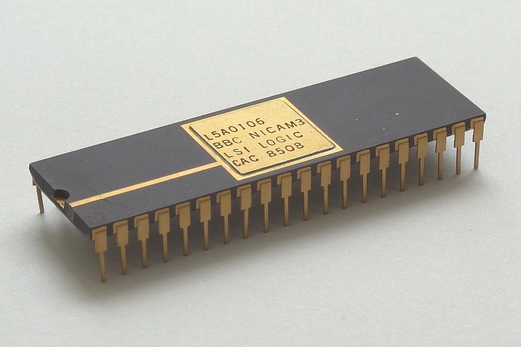
Prototype NICAM IC. The versions installed in the final working units were
rather plain-looking in comparison and lacked the gold trim!
Photo kindly provided by John Robinson.


During 1981 a test ‘loop’ was installed between London and Birmingham. The PCM feed to TXs was already being distributed to Birmingham from Broadcasting House. A temporary NICAM 3 link was added, feeding the signals that arrived by PCM back to London. This let the engineers monitor the performance of both the PCM and the new NICAM systems over a long path. They could stay in London and check the systems ran correctly. The arrangement avoided any risk that the feed to a transmitter might be lost or degraded if the experimental kit showed problems. One particular advantage of this arrangement related to the way in which the BBC planned to put NICAM into use. At that time most of the main and more powerful FM transmitters were fed by the established PCM distribution. However there were still a number of transmitters that relied on being fed via analogue links. These usually supplied the audio from a nearby main transmitter that was, itself, being supplied via PCM. It was realised that replacing these analogue ‘last leg’ parts of the system with NICAM would be a good way to extend improved performance to more transmitters.

So the plan was to install NICAM one step at a time, in phases. The first phase would install NICAM links that replaced some of the analogue weak links. That made more sense that starting off with replacing PCM with NICAM for connections that already worked far better than the remaining analogue parts of the network. The Birmingham-London loop was a convenient way to check that ‘PCM then NICAM’ routing would work reliably. Only after some of these links were installed to extend digital distribution to more transmitters, and the result shown to work well, would the PCM system itself start being replaced by NICAM.

RT.gif - 113Kb During 1981 however an interesting opportunity appeared to try out the NICAM 3 system in a more demanding and high-profile test. This arose out of the BBC Symphony Orchestra going on a tour, performing concerts in the Far East...

The concert chosen for the test was given in the Shanghai City Hall on 17th May 1981. The performance was given by the BBC Symphony Orchestra, conducted by Norman Del Mar. The image to the right shows the listing given in the Radio Times.

The audio was originally scheduled to be sent live from China back to the UK using a set of telephone relays to provide the requires stereo with a 15kHz bandwidth. But this proved difficult to arrange. So the decision was taken to send the live audio via a satellite link using one of the NICAM 3 coder/decoder pairs that had been built for the London-Birmingham tests. Inside China that simplified the requirement to just renting a video link from the Hall to the Peking Earth Station that could transmit via the satellite back to the UK.

One of the old NICAM 1 experimental coder/decode pairs were also put in place, just in case the NICAM 3 systems had problems. And the concert was also taped in Shanghai so that the recording could be broadcast at a later date in the UK.

The live transmission allowed a standard video link to successfully carry the NICAM 3 digital audio over a video link from the Hall back to Broadcasting House. It was the first “On Air” use of the NICAM 3 equipment designed by Robin Caine, Alan English, and John Robinson of the BBC’s Designs Dept.

When asked about the event, Robin commented:

The [Birmingham - London] trial was very successful, to the extent that it was decided to use it for the high-profile visit of the BBC Symphony Orchestra to China, where one concert, from Shanghai was to be relayed live to Radio 3 at noon London time. ...Nicam provided a solution by using a single video circuit all the way back, from Shanghai to Peking, then by satellite to Madley and so to London. The big risk was that video processors in this chain might seriously damage the waveform of the pulse stream and instructions went out to remove all such devices from the circuit. A comms engineer (Mike Rushmere) took one of the [NICAM 3] coders complete from the Birmingham racks, plus all the cards from the other [London] one to Shanghai, as well as the Nicam 1 prototype which had excelled for Elton John from Moscow.

On Sunday 17th May 1981 the whole design team went to BH Control Room and stood by - just as well because the signal suffered asymmetry making the negative pulses half the size of the positive ones. Slicing this bitstream requires two slicing points halfway up each of the positive and negative pulses. With one side half as high it required one of us to sit watching a scope and adjusting an attenuator to keep the slicer within the smaller pulse height and still above the noise on the other half. As a result the concert took place with a minimum of error problems. John Robinson had beavered furiously to improve the error concealment, so that instead of repeating a previous sample to cover for an erroneous one, a Z80 microprocessor was able to contrive a replacement (14-bit) sample which was an average of the previous and following samples. His new card was in the nick of time for this broadcast.

While we were in the Control Room Angus McKenzie, the hi-fi man from Hifi News rang up the BBC and was put through to the Control Room where he congratulated the BBC and the team on the extraordinary quality of the audio, regardless of the distance it had come.


The event was a historic “first” for the BBC, as shown by the front page from the BBC Ing Inf (Engineering Information) magazine.

IngInf5.gif - 167Kb


Angus McKenzie wrote a brief item about this concert in the issue of Hi Fi News dated July 1981. He then gave a much fuller description in the August issue. The sound quality of the live broadcast was excellent, and at that time amazing for such a long distance live event. At the end of the official programme the BBC SO added an encore. Angus McKenzie wrote:

“The Concert was held in the City Hall, Shanghai and included Vaughan Williams' 4th Symphony and Beethoven's Eroica Symphony, ending with an astonishing encore in which the orchestra really let themselves go, called 'Bearing the Good Tidings from Peking to the Mountain Villages'... Listening to my tape in retrospect, I am still just as impressed as I was the first time, not only with the playing of the orchestra, conducted by Norman Del Mar, but with the remarkable sound quality of the new digital link system.”


After the concert, the NICAM equipment was returned to the London - Birmingham test loop. Given the success, the next step was to start installing NICAM-3 in the FM distribution system.


NICAM takes over.
The first NICAM link joined Blaenplwyf to Wenvoe in the Autumn of 1983. For Radios 2 and 3 this took the PCM arriving at Wenvoe and transcoded it into NICAM which was then sent to Blaenplwyf. A number of the first NICAM links were made in this way, extending the existing PCM distribution. However the BBC engineers came up with a ‘cunning plan’. (Now where have I heard that phrase before?...)

The established PCM system multiplexed 13 audio channels into a 6336 kb/sec data stream. However by the early 1980s telecomms providers were starting to offer their own digital connection systems and it made sense to consider using these. One (CCITT standard) system provided 8448 kb/sec. So the decision was to adopt that to carry a ‘hybrid’ digital arrangement. This sacrificed one PCM channel but then allowed the remaining 12 PCM channels to be combined with 6 NICAM channels – all then carried by the 8448 k (i.e. 8 Meg) data stream. The advantage of this trick was that NICAM links could be added, and used at new sites to extend the network, without losing the PCM that existing transmitters depended upon. Transmitters that had used PCM could be converted to NICAM as and when convenient. So improvements could be done in a flexible way. Once all the transmitters could understand NICAM, the hybrid arrangement ended and PCM was removed. The 8448k stream then carried the output from four 6-channel NICAM encoders - so providing 24 audio channels (i.e. up to 12 stereo pairs).

NGpic.jpeg - 152Kb

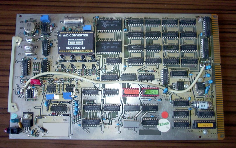
NICAM ADC card. Photo kindly provided by Neil Gilchrist


Each NICAM 3 encoder and decoder consisted of a set of circuit boards (cards) that were connected together to process the audio. The above photo shows one of the ADC cards used in the NICAM encoders.

TX1987.gif - 41Kb The first ‘hybrid’ 8 Meg links were bought into use feeding the Wrotham, Peterborough, Sutton Coldfield, and Holme Moss transmitters on the 15th of January 1986. Various detailed modifications and remedial work then had to be done to further extend the 8 Meg distribution. This let the NICAM reach other transmitters, reaching Sandale, Pontop Pike, Divis, and Kirk O’Shotts by the end of May 1986.

As with PCM, the installation of NICAM 3 to extend and improve the radio distribution network took place over about a decade, largely unannounced. From the public point of view the system simply got better as higher sound quality and stereo spread their availability.

The gradual approach came to a climax in 1993. That was when it was decided it was time to switch over from the ‘hybrid’ 18-channel PCM+NICAM mix to using the 24-channel NICAM. This process took a lot of careful planning and work. It required a number of co-ordinated actions and for various newly installed items to function well together.


The switchover started in May 1993 – around a decade after the first NICAM link came into use. The UK was divided into six geographic areas, and the change carried out one area at a time. Temporary ‘vision’ circuits were set up to provide the all-NICAM feeds to reach the transmitters whilst the hybrid links were still operating. This let the engineers install the new equipment at each transmitter and ensure it worked with the all-NICAM signal. Once that was done the normal link ceased sending the hybrid, and started sending the NICAM. The transmitters could then be switched to using the NICAM over the established path and the temporary circuits removed.

What could go wrong?... Well, as any engineer will expect, many detailed snags and problems did duly crop up during the process. Some were unexpected, like having to change components on some circuit boards to get them to work. Others were expected, like the ‘crash’ change of having to move both the feed to the area and its transmitters from the temporary to established connections in a synchronised way at the end of the process. Sometimes these ‘Oops!’ events wouldn’t have been noticed by listeners. But others my have caused widespread puzzlement. Like 40 mins of silence, followed by test tones from the Wenvoe transmitter. Or perhaps the Black Hill one radiating a ‘random re-mix’ of channels from its transmitters for a while! This has been called “Radio Random” and included stereo FM transmissions from two different (Medium Wave) stations on the left and right channels! If this was on Radio 3 FM, perhaps listeners thought it was a “First Performance” of a work by someone like Peter Maxwell Davis...

However despite these unplanned occasional entertainments, the process completed on 12th June 1993 when the PCM coders at Broadcasting House were switched off for the last time, and Wenvoe was the last FM transmitter to use the new all-NICAM feed. Since that time the entire BBC FM national network has been based upon the NICAM signals being fed to it. The last examples of the PCM equipment were given to the Science Museum in London.

If we compare FM transmitter statistics for 1970 and 1988 we can see just how much of an impact the PCM and NICAM distribution made on the ability to spread high quality stereo across the UK.

TXstats.gif - 44Kb

The above shows the numbers of FM broadcast transmitters the BBC used in the various regions of England in 1970. I’ve divided them by broadcast power (ERP) so you can also compare the numbers for main (high power) transmitters and low power subsidiary transmitters. You can see that as we move away from London and the South-East, the fraction of the provision in Stereo falls. I haven’t bothered to plot the results for the rest of the UK as they can be summarised quite easily. In 1970 none of the FM transmitters in Scotland, Wales, or Northern Ireland transmitted in stereo! By the end of the 1980s the number of transmitters around the UK had more than doubled. And all of them were broadcasting in stereo for Radios 2, 3, and 4 – except in the regions where, instead, the BBC regional broadcasts (e.g. Radio Scotland) were in stereo. The audio quality overall was far higher than in 1970.

In 1995 the main ‘backbone’ of the BBC distribution system was outsourced to Energis. This changed the basis of how the data was sent around the system. In practical terms this meant the audio was fed primarily between the studio/production centres, rather than being sent along the ‘chain’ from one main transmitter site to another. The system changed again in 2008 when it was “refreshed” and the outsourcing provided by Siemens. However throughout those changes, and up until now, the coding used for audio remains the same BBC-invented NICAM 3 digital coding.

These days people have largely forgotten the developments and little publicity was given to the behind the scenes work by BBC engineers. The roll-out of colour TV and the use of another variant of NICAM to provide stereo audio for analogue TV is much better known and appreciated. Yet in many ways the BBC engineers during a period of about 25 years produced a system that was revolutionary in a typically British way. Almost no-one even noticed how the BBC stereo FM distribution system covered the UK, and just accepted that the results were excellent. Good engineering tends to be taken for granted once it is established.

And most people still think of FM radio as ‘analogue’...

Jim Lesurf
7100 words
24th Nov 2011


Anyone who wants to know more about the technical details may wish to go and look at two excellent websites.


This article has only been possible due to the generous and patient help and advice of a number of ex-BBC engineers. In particular I would like to thank and acknowledge:

      David Birt, Robin Caine, Alan English, Neil Gilchrist.
      Keith Hayler, John Robinson, David Russell. and Graham Sawdy.

My thanks also to Martin Ellen who made the process possible, and for his work on the bbceng.info website.


prev.gif - 2352 bytes  ambut.gif - 3891 bytes  next.gif - 2248 bytes