Various factors can affect the sound quality of the radio broadcasts you can receive. This means that, in practice, deciding which form of broadcasting actually will give you the best results will depend on details like where you are, and what stations you like. This page looks at the main factors involved when comparing DAB (Digital Audio Broadcasting) and VHF/FM in the most of the UK. Starting with the most basic questions: Where are the closest transmitters to you, and how powerfully do they broadcast?
DAB Transmitters
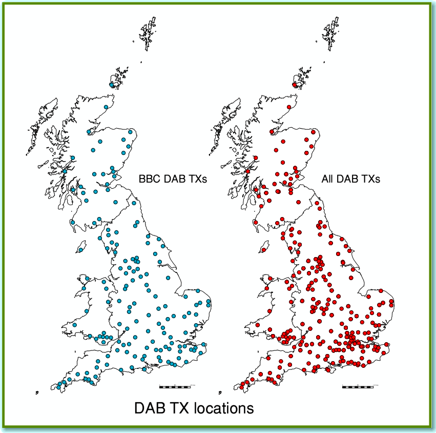
Figure 1 - DAB Transmitter Locations
Figure 1 shows the locations of all the DAB transmitters listed in Ofcom data on 1st Jan 2011. (The following maps are also based on the same Ofcom data sets of that date.) The left-hand map shows in blue the locations of the BBC transmitters in their national multiplex that carries the main BBC stations – Radio 1-7, etc. The right-hand map shows all transmitter locations including all the commercial services. You can see that the transmitters tend to be preferentially located in areas where the population density is highest. Some other areas – notable the North and West of Scotland and the center of Wales – are relatively sparsely served. However the maps in Figure 1 don’t show the ERP (Effective Radiated Power) levels of the individual transmitters.
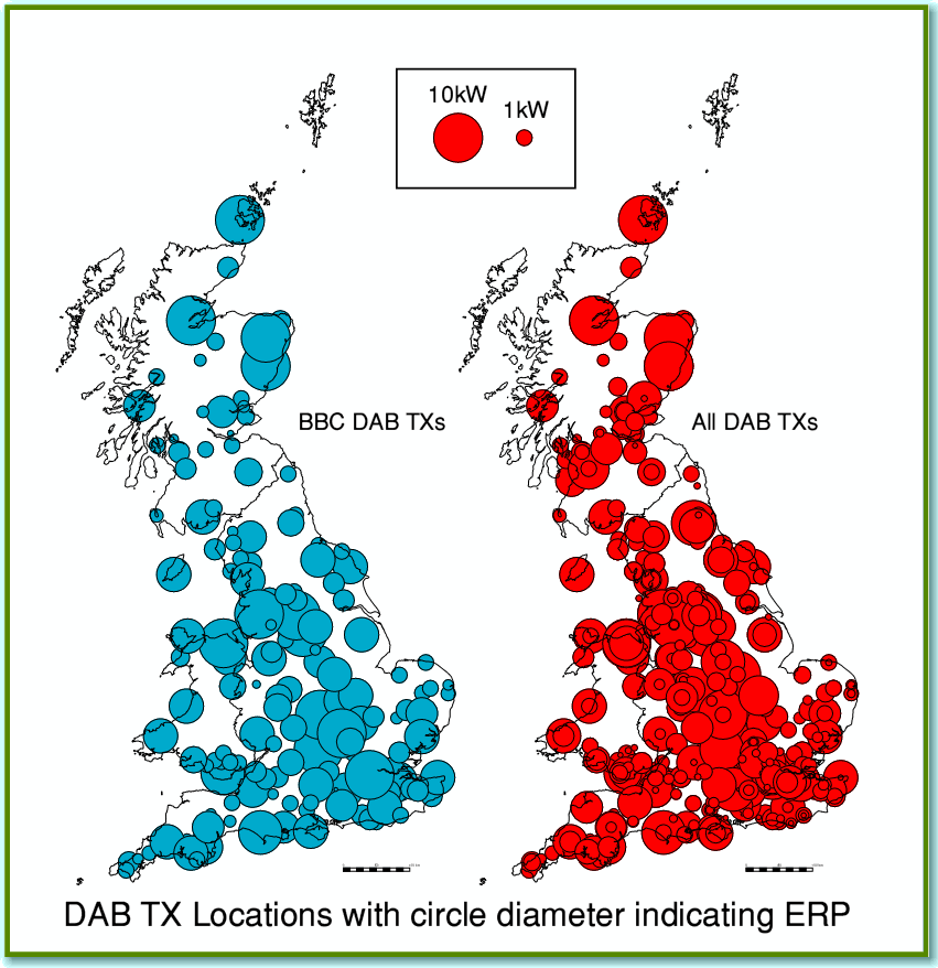
Figure 2 – DAB Transmitter locations and power levels.
Figure 2 plots the same DAB transmitters. But in this case the diameter of each circle indicates the transmitter’s power level. To do this I plotted each one with a diameter proportional to the square root of the transmitter ERP. I did this because – all else being equal – the diameter of the area covered by a transmitter would tend to scale in this way. However, please note that in practice this simple rule often fails. In reality many others things usually aren’t “equal” when you go from one location to another! Please also note that the circles shown in Figure 2 do NOT show the actual reception areas provided by the transmitters. The circles simply represent the relative transmitter powers. Despite these cautions we can see that the coverage is rather uneven. Some areas have many more transmitters, broadcasting more total ERP than others. And there still seems to be a relatively sparse coverage in central Wales and the North and West of Scotland.
VHF/FM Transmitters
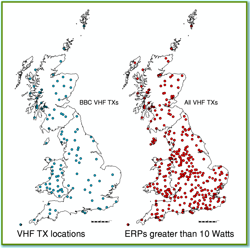
Figure 3 – VHF Transmitter Locations
Figure 3 shows the locations of the VHF/FM transmitters. In this case the left-hand map shows the BBC national transmitters. i.e. for stations like Radio 1-4 and BBC Radio Scotland, but omits the BBC ‘Local’ stations. The right-hand map shows all VHF transmissions including local and commercial, and so also includes some additional BBC services. For the VHF/FM maps all the transmitters above 10 Watts ERP are included. So some ultra-low power ‘fillers’ may be omitted.
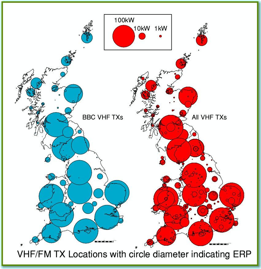
Figure 4 – VHF/FM Transmitter Locations and power levels
As with DAB the actual transmitter ERPs will matter, so I have also plotted Figure 4 which shows the individual ERPs in the same way as in Figure 2. Note that the scaling of the diameters of the circles is different in this case. This is because the ERPs of the main VHF/FM transmitters tend to be around 100 kW whereas 10kW is typical for the main DAB transmitters. Another difference between UK DAB and VHF is that DAB is transmitted with vertical (E-field) polarisation, but VHF/FM broadcasts generally use a mix of Vertical and Horizontal polarisations. This is a historic accident. Early BBC VHF transmissions were generally Horizontally polarised as that was felt at the time to give the best propagation. But as people started using portable and car radios with vertical ‘whip’ antennas it was decided to also transmit Vertical polarisation to give these listeners a better signal. Figure 4 uses whichever of the two Ofcom listed ERPs (vertical or horizontal) that is biggest.
As with the DAB maps, we need to bear in mind that the sizes of the circles shown are just meant to indicate the transmitter powers, not the actual areas covered. But even allowing for this, yet again, the coverage seems sparser in some areas than others. Again, the North and West of Scotland don’t do particularly well. But by looking at the maps you can get some idea regarding how well you can expect your location to be served compared with other places.
Receiver Behaviour
Having looked at the transmitter end of the broadcast link, let’s now consider the receiving end. Here the basic question is, “How much signal do we have to receive to obtain good quality results?”
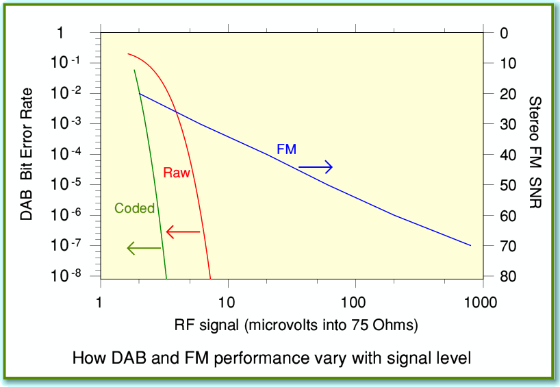
Fig 5 – Receiver performance as a function of received signal level
Figure 5 shows compares the basic behaviour of DAB and VHF/FM tuners (radio receivers). Here the received level is represented in terms of the RF voltage at the input of a tuner that has a 75 Ohm input impedance. The plotted results assume the tuners have low-noise, sensitive, and well designed RF/IF front-ends, so make optimum use of the input, and that there is a typical amount of ‘sky noise’ (i.e. natural environmental RF noise) for a quiet location.
In the past, when reviewing VHF/FM Stereo tuners it was routine for UK audio magazines to show a plot of how the output signal/noise ratio (SNR) they provided varied with the input VHF signal level. The best tuners gave performance similar to the blue line in Figure 5. Such plots are rarely seen nowdays in magazines, and and no-one seems to do equivalent in-depth measurements on the RF performance of DAB tuners! Not every tuner on sale will be as good as assumed for Figure 5. And the chances are that many portable and car radios are somewhat poorer than a good Hi-Fi tuner. As a result you may find your tuner may not provide results as good as in Figure 5. Alas, without the detailed measurements which used used to be available this has often become a case of “Yer pays yer money and yer takes yer choice!” when it comes to buying a tuner or radio!
It is difficult to compare DAB and VHF directly. The effect on the output audio of having a weak input signal is different for the two systems. For analogue VHF/FM the primary effect of too low an input level is noticeable background noise. So the blue line and the right-hand axis show how the audible SNR tends to vary with input RF voltage. Looking at this you can see that – with a good tuner – you tend to want almost 1mV of RF to get a SNR of around 70dB. But something more like 0·1 mV would provide around 60dB SNR. (This is for stereo. Mono VHF/FM requires much lower input levels, making life easier for mono portable radios!)
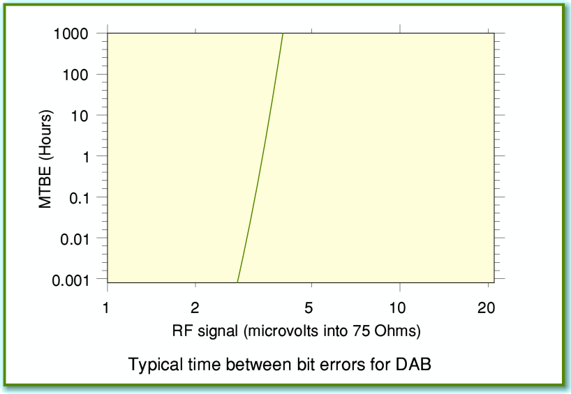
For DAB the presence of the steady natural RF background noise causes random bit-errors to occur as the tuner decides which of the bits in the digital stream are ‘1’s and which are ‘0’s. However if the received data bits are almost all being correctly recognised then the output SNR will be determined by the broadcast data. So when working with an RF level big enough to make bit-errors rare the SNR can easily be 80 to 90 dB if the broadcast is that good. Figure 5 shows two plots for DAB. One shows the ‘raw’ (red line) average bit error rate. i.e. what fraction of the bits picked up from the input data stream tend to be incorrectly identified due to the random noise. The other ‘coded’ (green line) plot shows the bit error rate after the received data is passed though the error detection and correction system used by UK DAB transmissions. This can’t fix all the errors, but can usually correct most of them. The error rates for DAB are shown by the right-hand axis. To make their meaning clearer we can use Figure 6.
Figure 6 – Mean Time Between Errors (coded) for DAB
This shows how long on average we would typically have to wait between individual bit-errors in the error-corrected output as a function of the input RF level. Bear in mind that this result is just the statistical average of how long we’d wait after one error until the next one popped up. In practice the individual errors would arrive randomly, so the time elapsed between any pair of them would be unpredictable. However looking at Figure 6 we can see that once we have a DAB RF input to a good tuner above about 5 - 10 microvolts we could expect most days not to hear any actual errors at all!
So perhaps the most interesting feature of the comparison is that we need almost 1 mV for good VHF/FM reception. But that 10 microvolts might be be OK for DAB. This is a 40dB difference in the required RF power levels, so quite a dramatic difference! If we look back and compare Figures 2 and 4 we can see that VHF/FM transmitters do broadcast with ERPs around 10dB higher than DAB transmitters. So on the above basis we could expect DAB reception around the DAB transmitters to be rather more reliable than that around the VHF transmitters. Alas, the above isn’t the entire story as you can tell from the way I used the phrase “all else being equal” earlier! In practice there are various other problems which can degrade the output audio from DAB or VHF/FM and affect their relative performance in a given listening location.
One other point to note is that if you look at the theory of radio ‘links’ you find that the efficiency of the power transfer from transmitter to receiver is frequency dependent since there is a wavelength-squared in the relevant equations. In the UK, VHF/FM uses carrier frequencies of around 100 MHz. DAB uses frequencies around 200 MHz. This means that if we compared DAB and VHF tuners using the same types of receiving antenna design (e.g. a dipole) we’d need four times the transmitter ERP for DAB than VHF if we want both to have their antenna pick up the same signal levels. (All else being equal, of course!) This gives DAB roughly a 6dB handicap that the previous analysis omits.
Various other factors then often come into play in real-world cases. The most common are:
Firstly, the higher frequency of UK DAB does not transmit though and around the internal structures of buildings quite as well as the lower frequency VHF. This can mean that indoor antennas and portable radios can be more fussy about where they will provide decent signal levels when you use DAB rather than VHF. The DAB signal also tends to fall away more swiftly once you move away from the transmitter and it goes ‘below the horizon’ since the higher frequencies don’t diffract so well around the surface of the globe. This tends to handicap DAB as you move more than couple of tens of kilometres away from the transmitter. But the effect will depend on the height of the transmitter and the shape of the land in your area, locations of buildings, etc.
Secondly, although the above did consider steady natural noise, one of the big enemies of VHF and UHF broadcasting is what is called ‘ignition interference’, along with all kinds of other man-made interference. The crackles and buzzes caused by drills, poor contacts in mains wiring, central heating switches, etc, etc. If you live in a city you are probably surrounded by loads of these unwanted ‘spark gap transmitters’. Each burst of RF they emit acts like a temporary but large rise in the background noise level. If you live in a location where the DAB signal is low, you might get good reception if these man-made sources of interference were suppressed. But when the keep bursting into song the result may be gargling or bubbling mud noised from your DAB tuner or radio. For VHF the effect is different. There you would hear crackling, buzzing, or clicking noises. Overall this is a matter of ‘swings and roundabouts’ since a relatively modest DAB signal may make reception reasonably immune to some ignition interference as the error correct may deal with it. Whereas ignition interference tends to be noticeable on VHF/FM, but sounds quieter when the interference is slight. In both cases the severity of the effects will depend where you live, and where you place your receiving antenna or portable radio.
Another more subtle effect is that the performance of a tuner or radio can be degraded if it is exposed to strong signals at RF frequencies close to the one used for the station you are trying to hear. This can reduce the sensitivity of the tuner or alter its performance in others ways. Sometimes this is obvious as interference, but at other times the tuner may simply seem not to work as well as it should and the poor performance blamed on some other reason. Again, since no-one seems to bother to publish measurements on the selectivity and rejection performance of Hi-Fi tuners or radios these days there isn’t much information available to guide the users and alert us to when one might be better than another at coping with such problems.
It is also worth mentioning that when the BBC did measurements some years ago they found it was surprisingly common for VHF/FM reception quality to be affected by multipath distortion. This is caused by receiving delayed reflections of the wanted signal along with the RF arriving via the direct transmitter-receiver path. The effect can be a relatively subtle form of distortion. The good news is that DAB is designed to reject multipath effect fairly efficiently.
From the above we can see that accurately predicting how easy you will find it to get good reception with a specific tuner and antenna in a specific place is difficult. However in general we can expect that a 10kW DAB transmitter should be able to cover a roughly similar area to a 100 kW VHF/FM one. But the devil is in the details, and for both systems you may find you are out of luck if you live in one of the areas relatively far from the transmitter locations plotted in Figures 1-4!
Jim Lesurf
2400 Words
4th Jan 2011
