Armstrong A20 Amplifier Circuit Diagrams
This page provides some technical information regarding the circuitry used in the A20 valve power amplifier. Note that the later 220 power amplifier is quite similar.
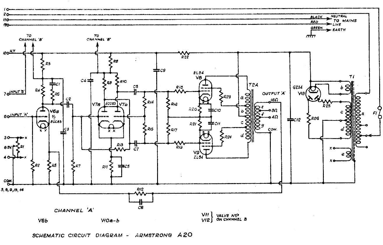
The image above is a small version of the schematic diagram of the A20 amplifier. Click on the image if you wish to see a larger version. When looking at the larger diagram, note that the numbers beside the wire-endings at the left of the diagram correspond to the pin numbers on the multiway connector which links the A20 to the associated pre-amplifier. Note also that only one channel (nominally channel A) of the stereo pair is shown on the diagram.
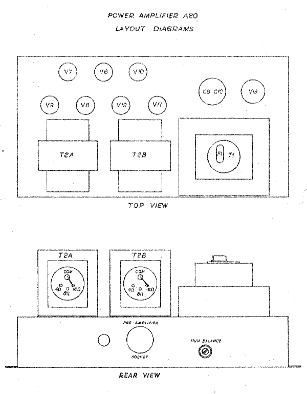
The diagram above shows the layout of the main components of the A20.
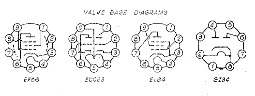
The above image shows the base pinouts for the valves used in the A20.
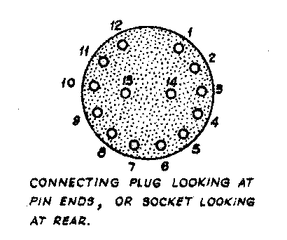
The above is taken from the pre-amplifier section of the manual for the PCU25 and A20. It shows the pin numbering for the multiway connector used to link the PCU25 preamplifier with the A20.

Content and pages maintained by: Jim Lesurf
using HTMLEdit and TechWriter on a StrongARM powered RISCOS machine.