Armstrong 500 Range Amplifier Circuit Diagrams
This page provides some technical information regarding the circuitry used in the 500 range amplifier. Note that the circuits used for the 400 range were almost identical to those in the 500 range. The same amplifier circuits were used in the 521 amplifier and in the amplifier sections of the 525 and 526 receivers.
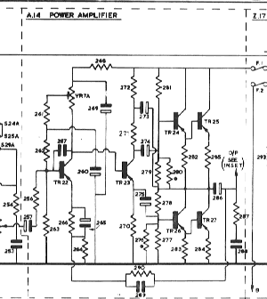
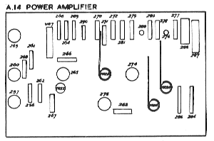
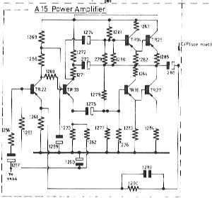
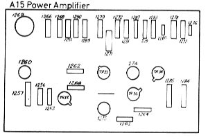
The early 500 range amplifiers use the A14 power amplifier board. This was replaced later on by the A15. (The 400 range used the A14.) The images below show small versions of the circuit schematic and board layouts for the A14 and A15. Click on the relevant image if you wish to see a larger copy. In each case the schematic only shows one amplifier channel, and the board is a component-side view.
The preamplifier section of the 500 (and 400) range was based upon the C16 preamp. The PSU was based upon the Z17 board. Their schematics and board layouts are shown below. As with the A16 and A17, click on an image if you wish to see a larger copy.
Note that the switching arrangement for the preamplifier sections was unusually complex due to the same set of transistors being used for both the line-level inputs (tape and radio) as well as for the RIAA (disc) preamplifier, and the inclusion of all the filtering, etc. As a result, the feeback arrangement is also switched depending upon the settings of the buttons along the fron of the unit.
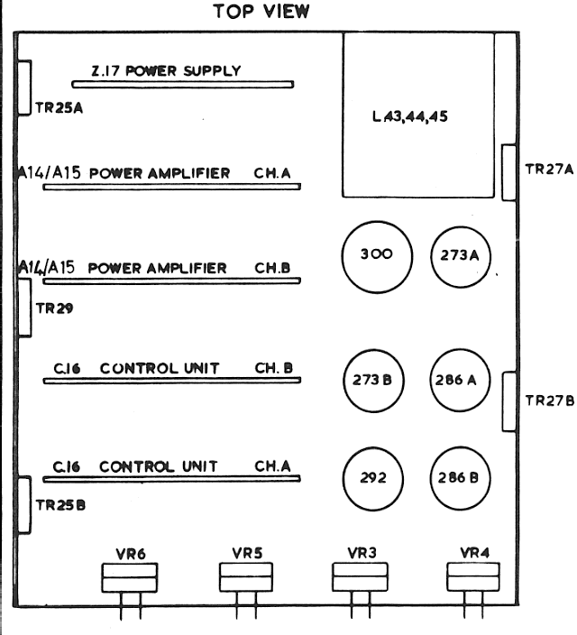
The image above shows the layout of the amplifier section of the 521 (and 421). The 525 and 526 (and also the 425 and 426) are similar, but with the chassis extended to the right to make space for the tuner sections.

Content and pages maintained by: Jim Lesurf
using HTMLEdit and TechWriter on a StrongARM powered RISCOS machine.
