The Armstrong 220 power amplifier


The 220 was the last valve power amplifier manufactured by Armstrong. As with the previous ‘A series’ units it was designed by Ted Rule. When the 200 range was released it featured integrated stereo amplifiers and tuner-amplifiers (receivers). These integrated units were convenient for purchasers who wanted compact, easy to operate, units that provided good performance at a competitive price. However it was felt that more demanding customers who wanted the best possible performance would continue to prefer to buy and use separate power and pre amplifier units. Hence the A20 and its PCU were restyled and renamed the 220 and 225 so as to offer these as part of the new range.

220front.jpeg - 55Kb


The appearance of the 220 was quite stunning with a red chassis and black carry-handles. This differed from the A20 which had a maroon chassis. The design used EL84 output valves in an ultra-linear arrangement, and was able to provide distortion levels below 0·1 percent at 1kHz for all power levels up to 12 Watts. As was common for valve amplifiers, it could deliver larger power levels but with increased levels of distortion. The unit provided H.T. and L.T. via a multiway connector to power the accompanying 225 pre amplifier .

220inuse.jpeg - 35Kb


The original valves used were: A GZ34 rectifier, three ECC83's, and four EL84's. The output transformers used grain oriented laminations and multi-sectional windings to ensure good performance.

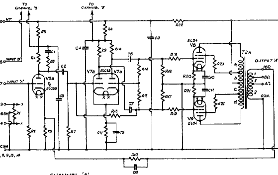
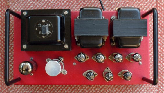
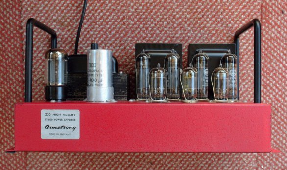
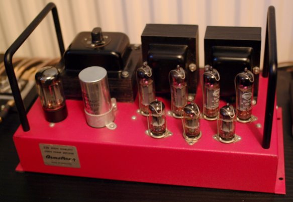
Specifications for 220 Power Amplifier
Rated Output 12 Watts (Output transformer tappings for 4, 8, and 15 Ohms)
Frequency Response 15Hz - 22kHz ±1dB Distortion <0·1%
Input sensitivity 410 mV for full rated output Output Valves EL84 ultra-linear’s
Noise -80dB Feeback 29dB
Power Response 20Hz - 18kHz ±1dB Damping Factor 53
Rise time 4 micro sec. Cross Talk -52dB at 1kHz
Stability Margin 18db (15 Ohm load) 18dB (with 0.1 micro F capacitor)


220diagsmall.gif - 12Kb


The above illustration shows a small version of the circuit diagram of the 220 Power Amplifier. If you wish to see a larger diagram, plus component list click here. Note that this also represents the A20.

The circuit topology used for the 220 was more complex than used in the power sections of the 221 and 222 and this, combined with a different choice of valves and larger output transformers, meant it was able to offer higher performance. The diagram above shows just one channel. One ECC83 double-triode was shared and used by both channels as their input stages. A second ECC83 triode-pair was then used in each channel to act as a phase splitter and to drive the EL84's.

220plan.jpeg - 43Kb


back.gif - 204 bytes homeblue.gif - 1289 bytes next.gif - 203 bytes

Colour photographs on this page
© J. B. Lovelock
Used by kind permission.

Content and pages maintained by: Jim Lesurf
using HTMLEdit and TechWriter on a StrongARM powered RISCOS machine.