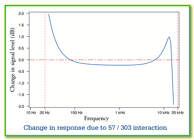
Interaction of QUAD 57 and 303
In general, loudspeakers tend to have an input (load) impedance that has a quite complicated frequency dependence. Unless the power amplifier (and connecting cables) have zero series/source impedance, the combination will alter the power/frequency response. The result may then have an audible effect upon the perceived tonal balance of the resulting music. The details of the changes will depend upon the specific choice of amplifier and speakers. For this reason, amplifier and speaker designers tend to assume that an ‘ideal’ power amplifier (and connecting cables) will have an output/series impedance small enough to have no audibly discernible effect. However in reality, some amplifiers depart significantly from this ideal.
For the purpose of this example I chose the QUAD 57 electrostatic loudspeaker and the QUAD 303 power amplifier. For understandable reasons, the 57 continues to be regarded by many people as an exceptionally good loudspeaker. Hence many continue to be used and enjoyed despite the design being some decades old. Since QUAD made the 303 amplifier at the same time as the 57 it seems reasonable to consider that they were intended to be used together, and some people still use and enjoy this combination. In some ways the combination is now regarded as a ‘classic’, and as such it makes an interesting example.
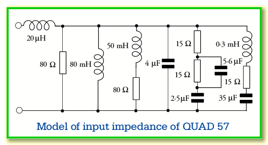
The above shows a circuit which roughly models the impedance/frequency behaviour of the 57 as a load. This circuit is a slightly modified version of an arrangement I have seen elsewhere and to me seems to fit the measured results (e.g. see http://www.quadels.com/quad_main.shtml) more reliably than other arrangements I have seen.
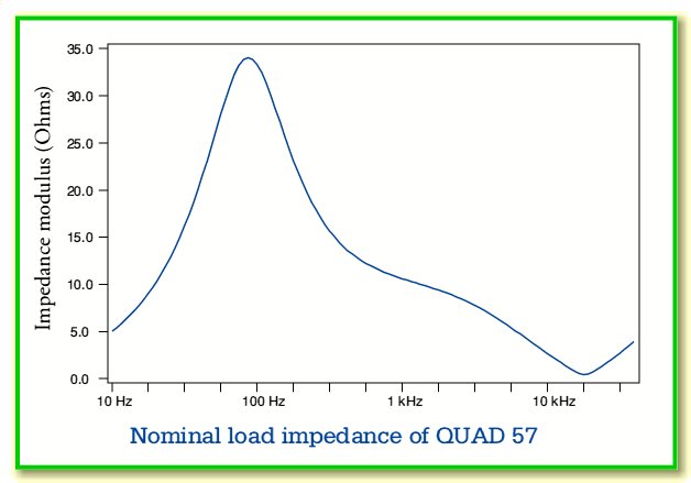
The above graph shows the impedance versus frequency of the load assumed for the 57. Note that this has a peak at low frequency, and also a quite severe dip at high frequency. This HF dip, the overall capacitance at high frequency, and a tendency for the transformer to saturate (not modelled or considered here) led to the speaker being regarded as a ‘difficult load’ when it was introduced.
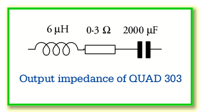
The above shows the circuit assumed for the output (series) impedance of the 303 power amplifier. These values are simply taken from the 303 handbooks and publicity material. Note that the series capacitance is present as the amplifier is a single-rail design and hence requires an output d.c. break capacitance.
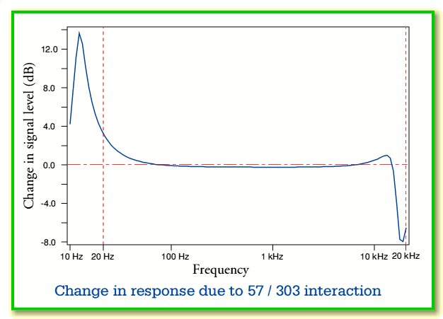
The above graph shows the change in response which occurs due to the interaction of the amplifier output impedance and speaker load impedance. Note that this does NOT show the actual response that is produced. It represents the change which will occur if the 303 is used instead of an amplifier which has a zero output impedance, but which is the same as the 303 in all other respects.
The above curve has three interesting features.
- There is a distinct peak at low frequency. Note that this is not due to an acoustic/mechanical resonance, but is due to a resonance between the output capacitance of the amplifier and the low-frequency inductance of the loudspeaker. For the values assumed during this analysis the resonance reaches a peak of over 13 dB at around 13 Hz.
- There is another peak at high frequency. The peak is just under 1 dB at around 13 kHz.
- Above the HF peak, the response falls into a deep resonant dip. This has its minimum of below -6 dB at around 20 kHz.
The above shows the same results, but now plotted with a changed vertical scale. This makes it easier to see where the response has been changed by a dB or so. It is a matter of debate and circumstances how large a change in response must be in order to be either audible or significant. In general, however, we can expect that changes of the order of a dB may be audible, and that changes larger than this may be significant in affecting the preferences of listeners. On that basis it seems reasonable to expect the changes produced by the 57/303 impedance interaction may well be audible.
Below there is a table of some example values from the response curve. Note that these are all relative to the level with an amplifier with zero output impedance. In practice the tonal balance would be in terms of the relative signal component levels at various frequencies. It is therefore worth noting that the midband tends to be reduced by around 0·2 dB, hence any rises and falls at higher or lower frequencies may be perceived relative to this, and the peaks at high and low frequency may thus be slightly emphasised.
| frequency
| 20 Hz
| 100 Hz
| 200 Hz
| 1 kHz
| 2 kHz
| 5 kHz
| 10 kHz
| 12 kHz
| 15 kHz
| 18 kHz
|
| change (dB)
| 3·85
| -0·08
| -0·18
| -0·23
| -0.22
| -0·10
| 0·47
| 0·85
| 0·03
| -8·07
|
It should be kept in mind that the results shown here are the product of a specific model, so may not be precisely accurate for a real 57/303 combination. However they should be reliable enough to serve as a general guide to the kind of effects that the amplifier's non-zero output impedance will have upon the behaviour of the system. Whether changes of the kind indicated here make the sound “better” or “worse” (or go un-noticed!) will depend upon the circumstances of use, and the preferences of the listener.
